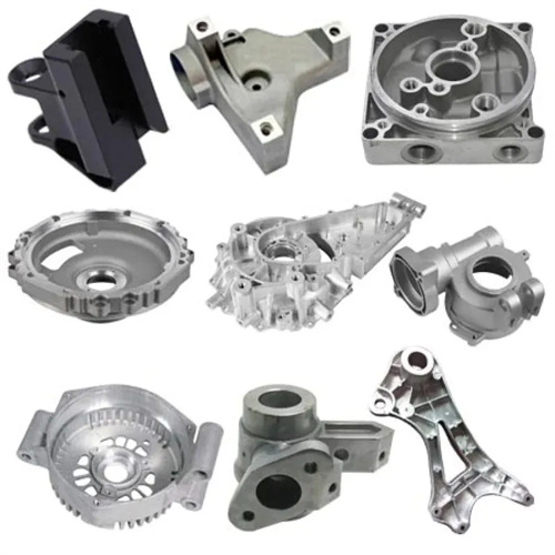
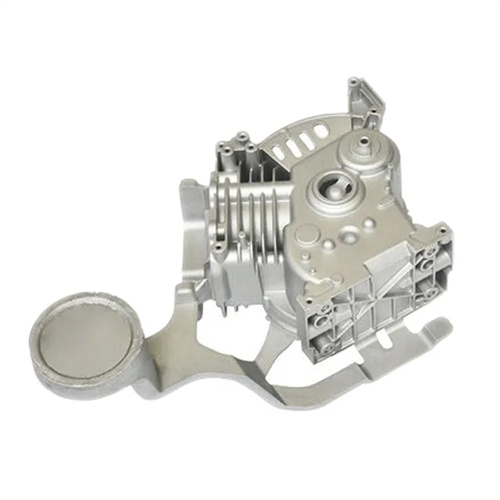
Die casting inserts
Die-casting inserts are a molding method in which a metal or non-metallic part is pre-placed into the mold cavity and then bonded to the molten metal through the die-casting process. The goal is to improve the local strength and wear resistance of the die-casting part or to achieve specific functions (such as conductivity and connection). Die-casting parts with inserts are widely used in the automotive, electrical, and mechanical industries, such as bearing sleeves in motor end caps and conductive pins in connectors. However, the quality of the bond between the insert and the die-casting directly affects product performance. A poor bond can lead to loosening, leakage, and other problems. Therefore, comprehensive optimization is required in terms of insert design, mold structure, and process control.
The insert’s structural design must ensure a secure bond with the die-cast part. Anti-slip features should be incorporated into the insert surface to enhance mechanical engagement with the molten metal. Common anti-slip features include knurling, grooving, drilling, and chamfering. For example, the outer surface of a cylindrical steel insert can feature a crosshatch knurling pattern with a knurl depth of 0.2-0.3mm and a pitch of 0.5-1mm, which can increase the bond strength between the insert and the aluminum alloy by over 30%. The insert’s geometry should be kept simple, avoiding complex protrusions or depressions to minimize mold design complexity and reduce positioning errors during insert placement. The insert’s length-to-diameter ratio should be minimal, generally no more than 5, to prevent tilting due to uneven force during die-casting. For thin inserts, the edges should be chamfered at 30°-45° to avoid sharp angles that can hinder molten metal flow and create cold shuts. Furthermore, the insert’s volume should be limited, generally not exceeding 20% of the total die-cast part volume, to avoid impacting molten metal filling and solidification.
The material selection and pretreatment of the insert are crucial to the quality of the bond. The insert material should have a similar coefficient of thermal expansion to the die-cast alloy to minimize stress caused by differential contraction during cooling. For example, 45 steel or stainless steel inserts are often used for aluminum alloy die-castings, while brass or low-carbon steel inserts are used for zinc alloy die-castings. The insert surface should be cleaned to remove oil, rust, and scale. Acid pickling, sandblasting, or ultrasonic cleaning can be used to ensure a surface roughness Ra between 1.6 and 6.3 μm to facilitate wetting and bonding with the molten metal. Steel inserts can be galvanized or phosphated to improve corrosion resistance and bond strength. Before placement in the mold, the insert should be preheated to 150-250°C (for aluminum alloy die-casting) or 100-150°C (for zinc alloy die-casting) to minimize the temperature difference with the molten metal and prevent rapid solidification of the molten metal on the insert surface, forming a cold shut.
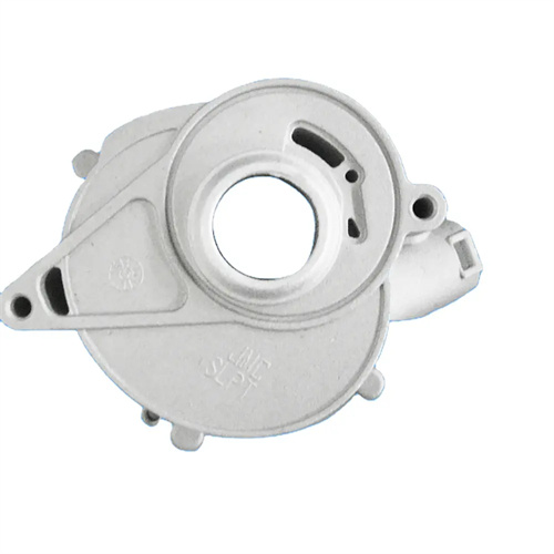
The mold’s insert positioning and fixation design must ensure precision and reliability. Dedicated positioning mechanisms, such as locating pins, locating sleeves, and magnetic devices, must be incorporated into the mold to ensure the insert’s accurate placement within the cavity, with a positioning error within ±0.05mm. Small inserts can be secured with spring clamps or magnetic fixation to prevent displacement by the molten metal during die-casting. Large inserts require rigid positioning, with a depth of at least 1/3 of the insert’s diameter. For example, the motor end cap bearing sleeve insert is positioned using upper and lower locating sleeves with a 20mm length (for a 30mm insert diameter) and a clearance of 0.02-0.03mm, ensuring coaxiality within 0.1mm between the insert and the end cap. The mold’s insert positioning areas must be wear-resistant, and carbide inserts can be used to extend the mold’s life. Furthermore, the mold should be equipped with an insert detection device, such as a limit switch or sensor, to ensure the insert is properly positioned before die-casting begins, preventing missed inserts and resulting in rejects.
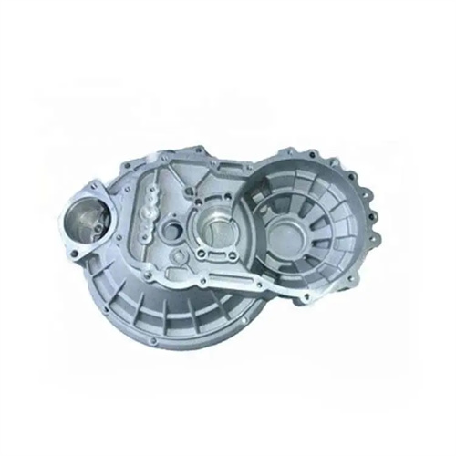
The control of die-casting process parameters has a significant impact on the bonding quality between the insert and the die-casting. The injection speed needs to be moderate. If it is too fast, the insert will be subjected to severe impact and shift or deform. If it is too slow, the molten metal will solidify too quickly around the insert, resulting in poor bonding. When die-casting aluminum alloys, the injection speed is generally 2-4m/s, and that of zinc alloys is 1-3m/s. The pouring temperature of the molten metal needs to be 10-20°C higher than when there is no insert to ensure that the molten metal around the insert can fully flow and solidify. The pouring temperature of aluminum alloys is 670-690°C, and that of zinc alloys is 420-440°C. The holding pressure and holding time need to be sufficient to ensure that the molten metal around the insert is fully compensated for shrinkage and reduce shrinkage. The holding pressure is 10%-20% higher than when there is no insert, and the holding time is extended by 0.5-1 second. For example, when die-casting an aluminum alloy shell with a steel insert, the injection speed is 3 m/s, the pouring temperature is 680 °C, the holding pressure is 80 MPa, and the holding time is 2 seconds. The density of the molten metal around the insert is significantly improved.
Post-cast insert processing further ensures product quality. After demolding, the insert’s position and fit must be inspected. Visual inspection can be used to check for exposed or misaligned inserts. Tap to check for looseness (a crisp sound indicates a good fit). If necessary, a tensile test should be performed to ensure the insert’s pull-out force meets design requirements (generally no less than 50N/mm²). For castings requiring tightness, a pressure test is required: apply a pressure of 0.5-1MPa to the insert-casting joint for 30 seconds to ensure no leakage. If looseness or poor fit is detected, the cause should be analyzed and measures implemented, such as adjusting the insert’s surface structure, increasing the preheating temperature, or optimizing process parameters. For inserts requiring high precision, machining can be performed after die-casting to correct dimensional and positional errors. However, excessive machining should be avoided to prevent damage to the seal and strength of the joint. Through strict quality control, die-cast parts with inserts can meet the high strength and reliability requirements.