Die castings to prevent deformation
Deformation of die-cast parts is a common quality issue in production, primarily manifesting as bending, warping, and twisting. This not only affects the product’s dimensional accuracy and assembly performance, but in severe cases can even render the casting scrapped. Deformation stems from internal stresses generated within the casting during the die-casting process, as well as external forces during cooling, demolding, and subsequent processing. Preventing deformation in die-cast parts requires comprehensive process control, from structural design and mold optimization to process control and post-processing. This reduces internal stresses and releases residual stresses, ensuring the shape stability of the casting.
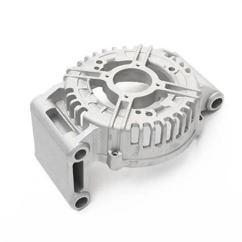
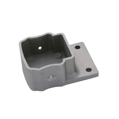
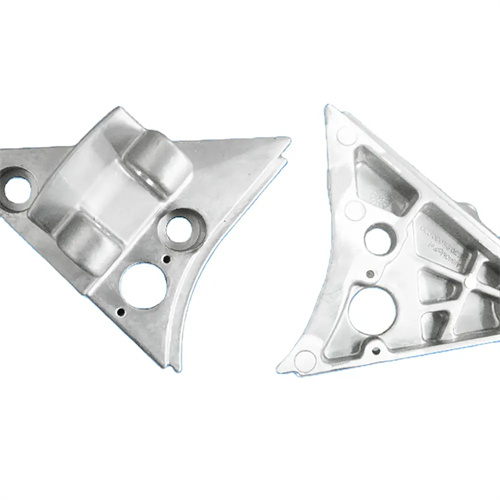
Proper casting structural design is a fundamental measure to prevent deformation. The casting structure should be as symmetrical as possible, with uniform wall thickness, avoiding sharp changes in wall thickness or narrow cantilever structures to reduce uneven shrinkage during cooling. For example, the middle of the long side of a rectangular shell is prone to warping. Cross-shaped reinforcing ribs with a thickness of 0.6 times the wall thickness can be added inside the shell to increase rigidity and evenly distribute stress. Casting corners should be sufficiently rounded (radius no less than 1mm) to avoid stress concentration caused by sharp corners, improve the flow and filling of the molten metal, and reduce localized shrinkage stress. For large flat castings, a wavy or stepped structure can be used instead of a completely flat surface, leveraging the structure’s inherent rigidity to resist deformation. For example, a shallow wavy design on an automobile engine cover reduces deformation from 2mm to less than 0.5mm.
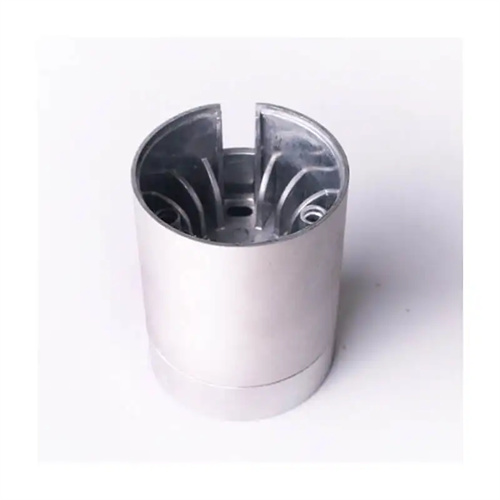
Optimization of mold design can effectively reduce deformation of castings. The mold cavity and core must ensure sufficient rigidity to avoid deformation under high pressure. The template thickness should not be less than 1/10 of the maximum size of the casting. For large molds, additional support columns are required. The cooling system design of the mold must ensure uniform cooling speed of all parts of the casting to avoid local overcooling or overheating. For example, the mold cooling water channel of box-type castings should be evenly distributed along the contour of the cavity, the water channel diameter should be 10-12mm, and the temperature difference between the inlet and outlet water should be controlled within 5°C to ensure consistent shrinkage of all parts of the casting. In addition, the mold ejection system needs to evenly distribute the ejection points, balance the ejection force, and have a slow and steady ejection speed to avoid warping of the casting due to uneven ejection.
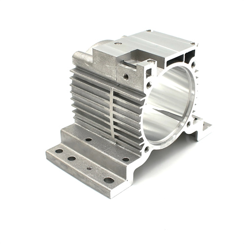
Precise control of die-casting process parameters is key to preventing deformation. Excessively high injection speeds can cause turbulence as the molten metal impacts the mold cavity, increasing internal stresses. Excessively low injection speeds can lead to insufficient filling. The appropriate injection speed should be selected based on the wall thickness of the casting: for thin-walled parts (thickness <2mm), the injection speed should be 4-6 m/s; for thick-walled parts (thickness >5mm), the injection speed should be 2-3 m/s. The injection pressure and holding pressure must be well matched. Insufficient holding pressure will result in low density and uneven shrinkage in the casting, while excessive holding pressure will increase internal stress. For aluminum alloy castings, the holding pressure is generally 60%-80% of the injection pressure. Mold temperature uniformity is crucial. A zoned temperature control system can be used to maintain a temperature difference of no more than 10°C between different zones of the mold cavity, reducing thermal stress caused by temperature gradients. For example, when die-casting a mobile phone midframe, with a stable mold temperature of 200±5°C, an injection speed of 5 m/s, and a holding pressure of 70 MPa, casting deformation can be controlled within 0.1 mm/m.
Post-demolding treatment of castings also plays a crucial role in reducing deformation. Freshly demolded castings contain significant residual stress, requiring aging treatment to eliminate this stress. Low-temperature aging (120-150°C for 2-4 hours) is suitable for aluminum alloy castings, while natural aging (room temperature for at least 24 hours) is suitable for zinc alloy castings. For castings requiring high precision, post-aging straightening treatment can be performed. Specialized fixtures apply a counterforce to induce plastic deformation, offsetting the original deformation. For example, after aging, a hydraulic straightening machine is used to straighten the flange surface of an automotive transmission housing. A pressure of 5-10 kN is applied for 30 seconds, resulting in a flatness correction from 0.3 mm to 0.1 mm. Furthermore, specialized tooling is required for the storage and handling of castings to prevent deformation caused by stacking, pressure, or collisions.
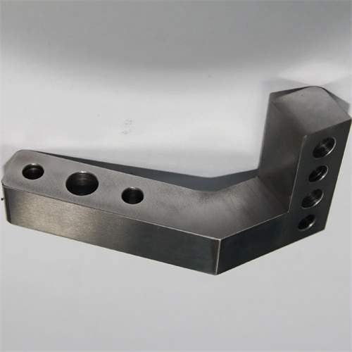
Controlling deformation during subsequent machining is also crucial. Machining can disrupt the casting’s inherent stress balance, leading to deformation. Therefore, the machining sequence should be rationalized, with the majority of excess stock removed first to release some stress before machining areas requiring higher precision. Appropriate cutting parameters should be employed, with small stock removal (ap = 0.1-0.3mm) and high rotational speeds (n = 3000-5000 rpm) to minimize the impact of cutting forces and heat on the casting. For thin-walled parts, auxiliary supports or vacuum fixtures should be used during machining to enhance rigidity and prevent deformation during machining. For example, when machining thin-walled aluminum alloy covers, vacuum fixtures are used for securing the parts. When milling flat surfaces, a stock removal of 0.2mm and a rotational speed of 4000 rpm are used, resulting in a flatness error of less than 0.05mm. By optimizing the machining process, deformation caused by subsequent machining can be controlled within the design tolerance.