Parting Surface Design of Die Casting Die
The parting surface design of the die-casting mold is a crucial part of the mold structure design. It not only determines the demolding method of the casting, but also directly affects the mold processing difficulty, production efficiency and the final quality of the casting. The parting surface refers to the plane where the fixed mold and the movable mold contact and separate from each other in the die-casting mold. Its design needs to comprehensively consider factors such as the casting’s geometric shape, dimensional accuracy, surface quality requirements, and production batch. A reasonable parting surface design can ensure that the casting stays smoothly on the movable mold side after the mold is opened, making it easier for the ejection mechanism to eject it smoothly, while reducing the occurrence of defects such as flash and burrs. On the contrary, if the parting surface design is unreasonable, it may lead to difficulty in demolding the casting, dimensional deviations, or even damage the mold, increasing production costs.
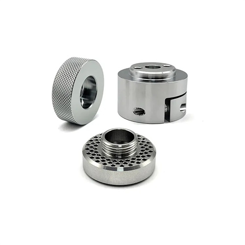
When designing the parting surface, the integrity and dimensional accuracy of the casting must be ensured first. The parting surface should avoid passing through important functional parts of the casting, such as bearing holes, sealing surfaces, etc., to prevent these parts from generating flash due to the presence of the parting surface, which will affect the assembly performance. For example, for die castings with precision threaded holes, the parting surface should avoid the threaded hole area to ensure the processing accuracy and sealing of the threads. At the same time, the position of the parting surface should ensure that the casting is accurately positioned in the mold cavity to avoid uneven wall thickness of the casting due to parting surface offset. In addition, the parting surface must also facilitate the processing and manufacturing of the mold, and try to use flat surfaces or regular curved surfaces to reduce complex processing steps and reduce mold manufacturing costs.
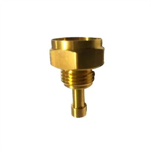
The shape design of the parting surface must match the contour of the casting to ensure sealing during mold closing and prevent leakage of molten metal. For castings with complex shapes, it may be necessary to use a combined parting surface, that is, a combination of multiple planes or curved surfaces, but the connection between the parting surfaces must be smooth to avoid sharp corners or right angles to prevent gaps when the mold is closed. For example, for castings with bosses and grooves, the parting surface can be set along the contour lines of the bosses and grooves so that the fixed mold and the movable mold can fit accurately, effectively preventing the molten metal from overflowing from the parting surface. At the same time, the roughness of the parting surface needs to be controlled within a certain range, usually requiring Ra≤1.6μm, to reduce friction resistance during mold closing and extend the service life of the mold.
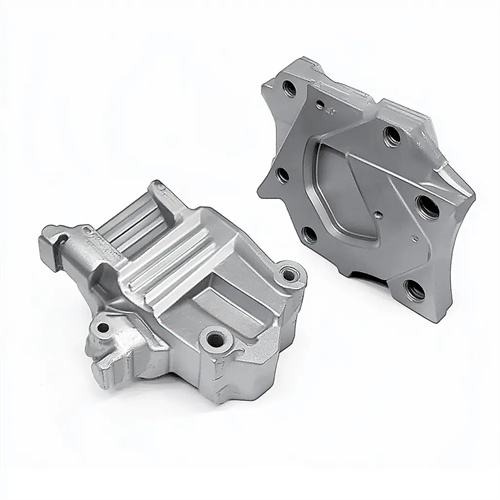
The design of the parting surface also needs to consider the needs of exhaust and overflow. During the process of molten metal filling the mold cavity, the gas and cold material in the mold cavity need to be discharged through the exhaust grooves at the parting surface to avoid defects such as air holes and cold shuts in the casting. Therefore, the parting surface should be set as close as possible to the last part of the casting to facilitate the arrangement of the exhaust grooves. For example, for box-shaped castings, the parting surface can be set at the edge of the box body, and exhaust grooves can be opened at the edge to allow the gas to be gradually discharged as the molten metal is filled. In addition, the connection between the parting surface and the exhaust groove should have a smooth transition to ensure that the gas can be discharged smoothly, while preventing the molten metal from entering the exhaust groove to form flash.
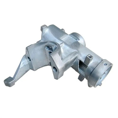
During the actual design process, the design of parting surfaces requires multiple verifications and optimizations. 3D modeling software can be used to construct a 3D model of the mold, simulating the mold opening and demolding processes. This allows verification of whether the casting will interfere with the mold and whether the parting surface meets venting and overflow requirements. For complex castings, simple wooden molds or 3D printed models can be prepared for trial assembly to verify the rationality of the parting surface. For example, when designing a die-casting mold for an automotive engine bracket, a company’s initial parting surface design caused the casting to deform during demolding. By adjusting the parting surface’s position, moving it from the center to the edge of the casting, and adding auxiliary parting surfaces, the deformation issue was resolved and the casting’s pass rate increased by 25%. This demonstrates that parting surface design is a process that requires continuous optimization and refinement. Only by comprehensively considering various factors can a reasonable and efficient parting surface be designed.