Basic structure of die casting mold
The basic structure of a die-casting mold consists of multiple functional components that work together to complete a series of die-casting processes, including filling, solidification, and ejection of molten metal. Its basic structure can be divided into six core parts: cavity assembly, pouring system, guide mechanism, ejection mechanism, cooling system, and mold frame. Each part has its specific function and role, which together ensure the smooth progress of die-casting production and the stability of casting quality.
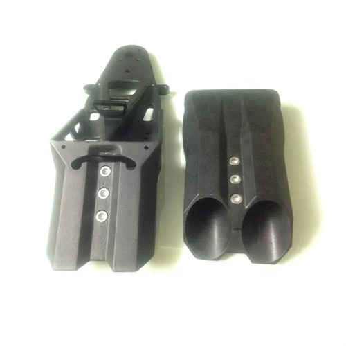
The cavity assembly is the core functional component of the die casting mold, directly determining the shape and size of the casting. It consists of a fixed die core and a movable die core. The fixed die core is fixed to the fixed die base plate, while the movable die core is mounted on the movable die base plate. When the mold is closed, the two tightly fit together to form a closed cavity, where the molten metal solidifies and forms the casting. The cavity assembly must be made of materials that are resistant to high temperatures, high strength, and wear. It is typically made of hot-working die steel (such as H13 and 3Cr2W8V), forged, heat-treated (hardness 44-48 HRC), and precision-machined. The surface roughness must be controlled below Ra0.8μm to ensure the casting’s surface finish. For example, the cavity surface of a die casting mold for aluminum alloy wheels must be precisely polished to ensure a smooth and flawless wheel surface, while also being able to withstand repeated exposure to molten metal at temperatures exceeding 700°C.
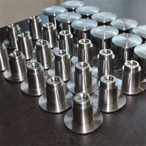
The gating system is the channel that guides molten metal from the pressure chamber into the mold cavity. It consists of a sprue sleeve, diverter cone, runner, and ingates. The rationality of its design directly affects the filling effect of the molten metal. The sprue sleeve docks with the die-casting machine’s pressure chamber, guiding the molten metal into the mold. The entrance is usually designed in a bell-shaped shape to facilitate the flow of molten metal. The diverter cone is located below the sprue sleeve and is used to divert the molten metal and guide it to the runner, preventing it from directly impacting the bottom of the cavity and reducing mold wear. The runner connects the sprue sleeve to the ingates and usually adopts a trapezoidal cross-section to ensure smooth flow of molten metal. The ingates are the final channel for molten metal to enter the mold cavity. Its position, shape, and size are determined by the structure of the casting and directly affect the filling speed and flow state. For example, for thin-walled castings, the ingates need to be designed as narrow and thin rectangles to increase the filling speed and ensure that the mold cavity is full.
The guide mechanism is used to ensure the precise positioning of the mold during the mold closing and opening processes and to prevent misalignment of the cavity components. It is composed of guide pins, guide sleeves, and locating pins. The guide pins are installed on one side of the movable or fixed mold, and the guide sleeves are installed on the other side. The guide pins and guide sleeves use a clearance fit (fit accuracy H7/h6) to ensure that the guide pins can be smoothly inserted into the guide sleeves during mold closing, achieving precise guiding. Large die-casting molds usually have 4-6 sets of guide pins and sleeves distributed at the four corners of the mold; small molds can have 2-4 sets. Locating pins are used to assist in positioning and are installed around the cavity to further improve mold closing accuracy. The guide mechanism requires regular lubrication. Usually, an oil groove is set on the guide sleeve and filled with high-temperature grease to reduce wear and extend service life.
The ejector mechanism’s function is to eject the casting from the cavity after the mold is opened. It consists of ejector pins, ejector rods, ejector plates, ejector plates, and reset rods. The ejector pins are in direct contact with the casting and are evenly distributed according to the casting structure. Their diameter and length must be determined based on the ejection force calculation to avoid deformation of the casting caused by bending or uneven ejection due to excessively thin ejectors. The ejector rods connect the ejector plate to the ejector cylinder of the die-casting machine to transmit the ejection force. The reset rod pushes the ejector mechanism back into position when the mold is closed to ensure accurate mold closing the next time. For large or complex castings, ejector components such as ejector plates and ejector tubes can also be used to ensure smooth ejection. For example, automobile engine cylinder block castings are large and heavy, and require the use of multiple sets of ejector pins and ejector plates to prevent deformation of the casting during ejection.
The cooling system and mold frame are crucial components of the die-casting mold. The cooling system, consisting of cooling channels, sealing rings, and water pipe connections, is distributed within the fixed and movable molds, controlling mold temperature through circulating cooling water. The cooling channels should be close to the cavity surface (15-25 mm away) and have a diameter of 8-12 mm. The channel density should be adjusted based on the wall thickness of the casting, with enhanced cooling in thicker areas. The mold frame, comprising the fixed and movable mold base plates, movable mold pads, and support plates, secures and supports the various functional components, ensuring overall mold rigidity and strength. The mold frame is typically constructed of 45 or Q235 steel and is machined to achieve sufficient flatness and verticality to ensure accurate alignment when the mold is installed on the die-casting machine. For example, the mold frame for a large die-casting mold can be 200-300 mm thick to withstand the immense clamping forces during mold closing and prevent deformation.