Design of die casting mold base
As the fundamental support structure of the mold, the die-casting mold base performs crucial functions, including securing the cavity, guiding the mold, and transmitting clamping force. The rationality of its design directly impacts the mold’s lifespan, production efficiency, and die-casting quality. Compared to plastic mold bases, die-casting mold bases must withstand higher temperatures (typically 150-300°C), greater clamping forces (up to several thousand tons), and the impact loads of molten metal. Consequently, they place more stringent requirements on material selection, structural strength, and guiding accuracy. The design of die-casting mold bases prioritizes rigidity, supplemented by heat dissipation and ensuring ease of assembly and disassembly. Through systematic structural planning, these bases ensure stable operation in high-pressure and high-temperature environments.
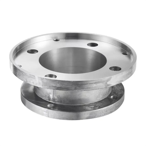
The overall structure of the die frame is the core framework of the design. A standard die-casting die frame typically consists of basic components such as the fixed die base plate, movable die base plate, fixed die sleeve, movable die sleeve, support plates, and spacers. The connection method of each component is determined by the clamping force: small and medium-sized molds (clamping force <500 tons) can be connected with bolts, while large molds (clamping force >1000 tons) require additional locating pins and reinforcing ribs to prevent deformation under stress. The fixed die base plate is directly connected to the fixed die plate of the die-casting machine. Its thickness is calculated based on the mold weight and clamping force, generally 1/8 to 1/10 of the maximum mold dimension. The material used is 45 steel that has been quenched and tempered (hardness 28-32 HRC). The movable die base plate is connected to the fixed die plate of the die-casting machine and requires ejector holes to accommodate the die-casting machine’s ejector mechanism. The hole positioning accuracy is controlled within ±0.1mm to prevent unbalanced loading during ejection. The support plate (also known as the pad) is located between the movable mold sleeve and the pad, and bears the pressure transmitted by the cavity. Its thickness must be calculated through strength verification to ensure that the deflection does not exceed 0.05mm/m.
The design of the guiding and positioning system is crucial for ensuring mold clamping accuracy. The guiding mechanism of a die-casting mold base typically utilizes a guide pin and guide bushing combination. The number of guide pins is determined by mold size: small and medium-sized molds require four guide pins, while large molds require six to eight. These pins are distributed at the four corners and the midpoints of the long sides to ensure uniform guidance. The guide pin and guide bushing have a matching accuracy of H7/f7, with a clearance of 0.02 to 0.05 mm. This ensures accurate guidance while preventing sticking caused by thermal expansion at high temperatures. The guide pins are made of 20CrMnTi, carburized and quenched (surface hardness 58 to 62 HRC), with a surface roughness of Ra ≤ 0.8 μm to reduce wear. The guide bushings are made of a self-lubricating copper alloy (such as ZCuSn10Pb1), which reduces guide friction. In addition to the guide pins and guide sleeves, a precision positioning mechanism is also required, such as a tapered positioning pin or positioning block with a matching clearance of ≤0.01mm, to eliminate the mold closing error caused by the guide pin clearance and ensure that the cavity misalignment is ≤0.03mm. It is particularly suitable for precision die-casting molds.
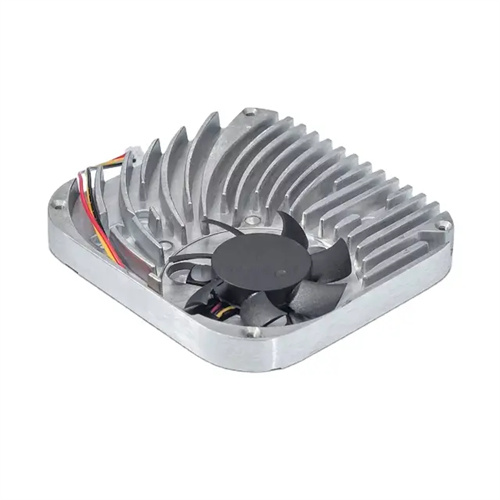
Heat dissipation and thermal insulation are essential measures for die-casting mold frames to adapt to high-temperature environments. During the die-casting process, the high temperature of the molten metal (650-700°C for aluminum alloys) causes the mold temperature to rise continuously. If this heat cannot be dissipated in time, it can cause thermal deformation of the mold frame and affect the cooling rate of the die-casting. Therefore, the mold frame requires a cooling system. Cooling channels should be drilled in the fixed and movable mold sleeves. The channel diameter should be 8-12 mm depending on the mold frame size, with a spacing of 50-80 mm. The inlet and outlet temperature difference should be controlled within 5-10°C. The cooling channels should avoid the mold cavity and guide pin holes and be at least 15 mm away from the cavity surface to prevent excessive local cooling. For die-casting of high-temperature alloys (such as copper alloys), an insulation board made of mica or asbestos board with a thickness of 3-5 mm is required between the fixed mold base plate and the fixed mold sleeve to reduce heat transfer to the die-casting machine. Furthermore, cooling fins can be installed on the bottom of the movable mold base plate to increase the heat exchange area with the air and help reduce the mold frame temperature.
Verifying the strength and rigidity of the mold base is a prerequisite for safe operation. Uneven distribution of clamping force on the mold base can lead to localized stress concentrations. Therefore, the mold base must be simulated using finite element analysis software (such as ANSYS). Focusing on verifying whether the maximum stresses in the fixed and movable mold plates exceed the material’s allowable stress (180 MPa for 45 steel after quenching and tempering). For large molds, calculating the support plate’s deflection is crucial. The formula is: deflection = (5 × clamping force × span³) / (384 × elastic modulus × section moment of inertia). The deflection must be ≤ 0.1 mm; otherwise, the support plate thickness must be increased or reinforced with ribs. As a key component supporting the movable mold plate, the spacer must be of a height that ensures coordination between the movable mold base and the die-casting machine’s ejector mechanism. Furthermore, the spacer’s cross-sectional area must meet the following criteria: cross-sectional area ≥ clamping force / material compressive strength (the compressive strength of cast iron spacers is 200 MPa). In addition, the specifications of each connecting bolt of the formwork must be determined through strength calculations, and the pre-tightening force must reach 60%~70% of the bolt’s yield strength to prevent loosening during operation.
Balancing standardization and customization of mold bases is a key strategy for improving design efficiency. Prioritizing national standard mold bases (such as GB/T 4678) can shorten design cycles and reduce manufacturing costs. Standard mold base sizes cover common clamping force ranges (100-3000 tons) and mold platen specifications. However, for die-cast parts with specialized structures (such as large, complex housings), customized designs based on the standard mold base are necessary. This can include adding intermediate sleeves to achieve multi-layer cavities and providing space for side core pulls. The lifting and installation design of the mold base also require simultaneous consideration. Lifting holes are provided on the fixed and movable mold bases. Hole diameters range from M20 to M48, depending on mold weight, and are symmetrically distributed to ensure balanced lifting. The location and size of the mounting holes must align with the die-casting machine’s fixed plate, with a hole spacing tolerance of ±0.1mm to ensure smooth mold installation. By combining standardized modules with customized design, design and manufacturing efficiency can be maximized while maintaining mold base performance.