Structure and classification of pouring system
The structure of the pouring system is the physical basis for achieving efficient molten metal transportation. Its core function is to smoothly guide the molten metal in the pressure chamber of the die-casting machine into the mold cavity. A complete conveying channel is formed by the collaboration of multiple functional components. The typical structure includes four basic parts: the gate sleeve, the sprue, the runner, and the ingates, supplemented by auxiliary structures such as overflow grooves and exhaust grooves. The gate sleeve serves as the interface between the pressure chamber and the mold, and needs to cooperate precisely with the injection rod to prevent the leakage of molten metal; the sprue vertically connects the gate sleeve and the runner, and is responsible for introducing the molten metal into the diversion area; the runner plays a role in diversion and pressure stabilization, distributing the molten metal to each ingate; the ingates are the last gateway for the molten metal to enter the cavity, and its size and shape directly determine the filling effect.
Based on the casting structure and production requirements, gating systems can be divided into two categories: single-cavity and multi-cavity. Single-cavity gating systems are suitable for large or complex castings, such as engine blocks and transmission cases. They feature a dedicated runner layout that allows for targeted optimization of the filling path. For example, large vehicle frame castings often utilize a “central feed + multi-branch runner” structure to ensure that the molten metal reaches all cantilevered parts simultaneously. Multi-cavity gating systems are used for the mass production of small parts (such as connectors and gears), requiring a balanced runner design to ensure consistent filling conditions across cavities. Runner layout can be categorized as series, parallel, or hybrid. Series runners have a simpler structure but can result in significant variability in filling time between cavities. Parallel runners use a main runner to independently feed each cavity, resulting in better balance. Hybrid runners combine the advantages of both and are suitable for combination molds with cavities of different sizes.
According to the connection method between the inner gate and the cavity, the pouring system can be divided into direct gate, side gate, ring gate and other types. Direct gate refers to the inner gate opened directly on the large plane or end face of the casting. It is suitable for thick-walled or large castings. The advantages are small pressure loss and strong shrinkage compensation ability, but obvious gate marks will be left on the surface of the casting and need to be removed through subsequent processing. The side gate is opened on the side or parting surface of the casting. It is suitable for small and medium-sized parts, such as home appliance accessories. Its advantages are easy removal of the gate and good surface quality, but the pressure transmission efficiency is low. The ring gate is set around the cylindrical part of the casting (such as the bearing seat), which can achieve 360° uniform filling and significantly reduce segregation defects, but the runner metal consumption is large and it is suitable for high-precision parts.
Specialized structural castings have necessitated specialized gating systems. For slender rods (such as door handles), slot gates are used to uniformly feed material along their length to prevent bending and deformation. For shell components with deep cavities, submerged gates are used to feed material from the inner wall to minimize surface damage. For thin-walled tubular components, fan gates are used to achieve wide filling and reduce the risk of cold shuts. Furthermore, gating systems are specifically designed for processes such as high-pressure die casting (HPDC) and squeeze casting. HPDC systems emphasize high-speed filling, with ingates reaching speeds of 50-80 m/s. Squeeze casting, on the other hand, requires low flow rates and high pressures, often employing flat gates with delayed pressurization mechanisms.
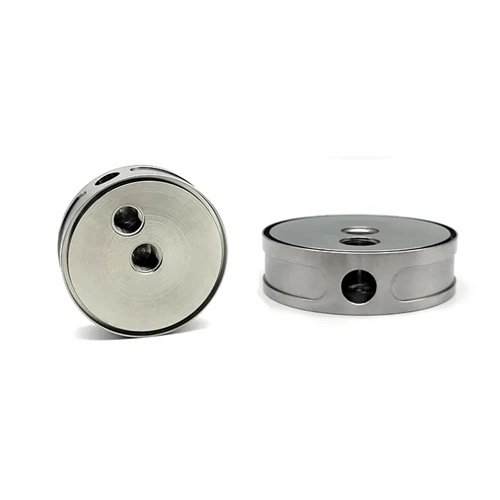
The structure and classification of gating systems don’t exist in isolation; practical applications require flexible combinations. For example, a company manufactures motor end caps (discs with bearing holes) that utilize a composite structure of “sprue + annular runner + three side gates.” The annular runner ensures circumferential pressure balance, while the side gates avoid the bearing hole area, ensuring uniform filling while minimizing impact on critical areas. Advances in 3D printing technology have significantly lowered the manufacturing threshold for complex gating systems, enabling the use of traditionally difficult-to-machine special-shaped runners (such as variable-section runners and biomimetic branching runners), offering greater potential for improving casting quality.