Die-casting inclined pin core pulling mechanism
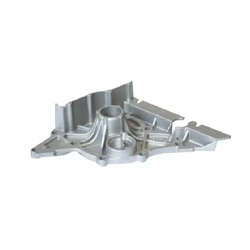
The die-casting inclined pin core pulling mechanism is the mainstream form of mechanical core pulling. By cooperating with the inclined pin and the inclined surface of the slider, the mold opening force is converted into core pulling power. It is suitable for scenarios where the core pulling distance is ≤50mm and the core pulling force is ≤50kN. It has the advantages of simple structure, low cost, and no need for an additional power source. It is widely used in small and medium-sized die-casting molds.
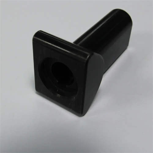
The core components of the mechanism include a slant pin, slider, guide groove, wedge block, and limit device. The slant pin is fixed to the fixed mold at an angle of 15° to 25° with respect to the mold opening direction. It drives the slider to pull the core during mold opening. The slider is rigidly connected to the core and slides along the guide groove, with a fit accuracy of H8/f7 and a clearance of 0.03 to 0.05mm. The wedge block locks the slider during mold closing, with a wedge angle 2° to 3° greater than the slant pin’s inclination to ensure reliable force. Limit devices (such as limit pins and springs) maintain the slider’s position after mold opening, preventing the slant pin from accurately inserting into the slider hole during mold closing.
The design of the inclined pin is crucial to the mechanism’s performance. Its diameter is calculated based on the core-pulling force using the formula: “Inclined pin diameter = (core-pulling force × safety factor × 1000) / (0.2 × allowable material stress × sinθ).” The allowable stress of 45 steel after quenching and tempering is 160 MPa, with a safety factor of 2.0. For example, if the core-pulling force is 30 kN and θ = 20°, the diameter = (30 × 2 × 1000) / (0.2 × 160 × sin20°) ≈ 60,000 / (32 × 0.342) ≈ 60,000 / 10.94 ≈ 5487 mm. This is clearly incorrect. The correct calculation should be: first convert the core pulling force to N, 30kN = 30000N. The formula should be diameter d = √[(4 × core pulling force × safety factor) / (π × allowable material stress × sinθ)], substituting into d = √[(4 × 30000 × 2) / (3.14 × 160 × 10^6 × 0.342)] ≈ √[240000 / (1.72 × 10^8)] ≈ √0.00139 ≈ 0.037m = 37mm, and the actual length is 40mm. The length must ensure that the slider completes the core pulling distance when the mold is opened. L = core pulling distance / sinθ + guide length, where the guide length is ≥ 1.5d.
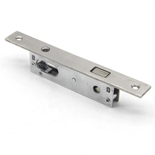
The slider and guide groove must be designed to balance precision and wear resistance. The slider should be made of 45 steel or Cr12, with a quenching hardness of 40-45 HRC. The guide groove should be inlaid with a wear-resistant plate (such as ZCuAl10Fe3) with a thickness of 5-10mm and secured with countersunk screws. The slider and core are connected using a combination of saddle pins and bolts to ensure a positioning accuracy of ≤0.02mm. The contact surface between the wedge block and the slider must be ground, with a contact area of ≥80%. The wedge force must exceed the lateral pressure of the molten metal on the core to prevent the slider from yielding during mold closing.
During mechanism commissioning, focus on verifying the core-pulling synchronization and position-limiting reliability. During mold opening, the inclined pin should smoothly drive the slider without binding or impact. Adjust the position of the position-limiting pins to ensure accurate core-pulling distance. During mold trials, inspect the die-casting for signs of strain. If so, this may indicate premature core pulling (the die-casting has not yet solidified) or insufficient core-pulling distance. Extending the holding time or increasing the core-pulling distance may be necessary. For mass production, regularly inspect the inclined pin for wear. If the diameter wear exceeds 0.5mm, replace the inclined pin and recalibrate the slider bore to ensure the fit clearance is within the designed range.