Design of die-casting core-pulling mechanism
The die-casting core pulling mechanism is a key device for processing the complex molding surfaces of die-casting parts. It is mainly used for molding side holes, side recesses, bosses and other structures on die-casting parts. When these structures cannot be directly demolded through the mold opening action, the core must be pulled out with the help of the core pulling mechanism before or during the mold opening process to ensure the smooth demolding of the die-casting parts. The design of the core pulling mechanism must take into account the smoothness of movement, compact structure and power reliability. According to the power source, it can be divided into four categories: manual core pulling, hydraulic core pulling, pneumatic core pulling and mechanical core pulling. Among them, hydraulic core pulling is widely used in large and medium-sized molds and complex core pulling scenarios due to its high power and convenient speed regulation, while mechanical core pulling is suitable for small molds or occasions with small core pulling force.
The core-pulling mechanism is basically composed of a core, a core-pulling power element, a transmission mechanism, a guide, and a locking device. The core directly forms the side holes or undercuts of the die-cast part. Its structure must precisely match the shape of the die-cast part. The material is usually H13 steel, which is quenched to a hardness of 48-52 HRC and a surface roughness of Ra ≤ 0.8μm to reduce friction during core pulling. The transmission mechanism is responsible for transmitting power to the core. Common forms include inclined guide pin transmission, rack and pinion transmission, and direct hydraulic cylinder drive. Inclined guide pin transmission is suitable for applications with a small core-pulling distance (generally ≤ 50mm). The mold opening force is converted into core-pulling force through the cooperation of the inclined guide pin and the slider. It has a simple structure but limited core-pulling force. Rack and pinion transmission is suitable for scenarios with a large core-pulling distance or when rotary core pulling is required, and can achieve smooth core pulling over a longer distance.
The guide mechanism is a crucial component for ensuring the precision of core pulling movements. It typically consists of a slider, guide rail, and guide slot. The slider is rigidly connected to the core and moves in a straight or curved pattern along the guide slot. The slider and guide slot are designed to meet a precision of H8/f7, with a clearance of 0.03-0.05mm to ensure smooth movement and prevent wobbling. A lubricating oil groove is required at the bottom of the guide slot, which should be regularly filled with high-temperature grease to reduce wear. The locking mechanism secures the slider during mold closing, preventing the core from being pushed apart by the pressure of the molten metal. Common locking mechanisms include a wedge block and a locking pin. The wedge angle of the wedge block should be 2-3° greater than the angle of the guide post to ensure secure locking during mold closing. The material used is 45 steel, hardened to a hardness of 40-45 HRC. The contact surface with the slider is ground to ensure a tight fit.
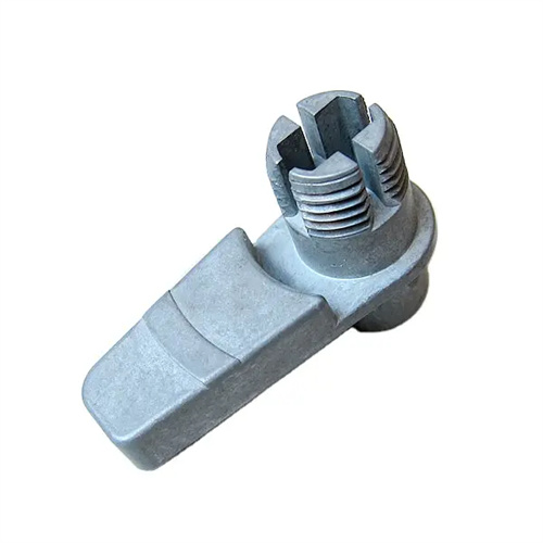
The design of different core-pulling mechanisms needs to be optimized based on specific scenarios. For linear core pulling (such as side-hole core pulling), if the core pulling distance is ≤30mm, inclined guide pin core pulling is preferred. The inclined guide pin should be tilted at an angle of 15° to 25°. A large angle can easily cause the slider to be subjected to excessive force during core pulling, causing it to jam. When the core pulling distance is 30-100mm, hydraulic core pulling can be used. The cylinder stroke should be 10-15mm greater than the core pulling distance to ensure complete core extraction. For rotary core pulling (such as threaded core pulling), a gear transmission mechanism must be designed. The gear module is determined based on the core pulling force calculation and is generally 2-5mm. The transmission ratio must ensure that the core rotation angle meets the demolding requirements. A limit device should also be provided to prevent the core from excessive rotation. For complex multi-directional core pulling, a linked core pulling mechanism is required. Multiple core pulling actions are linked through connecting rods or cams to ensure that each core is pulled in a preset sequence to avoid interference.
The safety design and debugging verification of the core pulling mechanism cannot be ignored. Core pulling limit devices, such as limit blocks, travel switches, etc., need to be set to prevent damage to the core or mechanism due to excessive core pulling. The response accuracy of the travel switch must reach ±0.5mm. For hydraulic core pulling systems, a pressure relay must be installed. When the core pulling force exceeds the set value (generally 1.2 times the rated core pulling force), the machine will automatically shut down to protect the mechanism from overload damage. During the mold debugging stage, it is necessary to verify the coordination of the core pulling action through trial molds, measure the matching of the core pulling time and the mold opening time, and ensure that the core pulling is carried out after the die casting is completely solidified to avoid deformation of the die casting during core pulling. For large core pulling mechanisms, dynamic balance tests are also required to prevent the inertial force generated during high-speed core pulling from causing mold vibration and affecting the quality of the die casting.