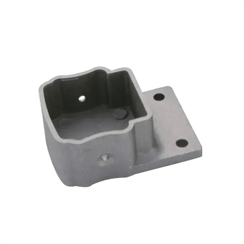
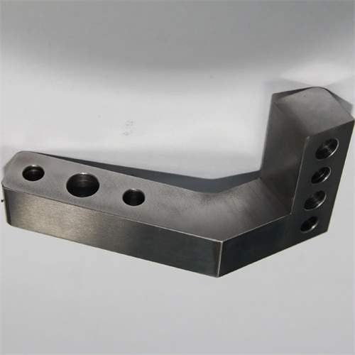
Die-casting supporting and fixing components are the “skeleton” of the mold structure. Their core function is to withstand the clamping force and impact of the molten metal during the die-casting process, and precisely position functional components such as the cavity and core in their preset locations, ensuring stable operation of the mold under high pressure and high temperature. These components include seat plates, spacers, support plates, and locating pins. Their design quality directly affects the rigidity and lifespan of the mold, as well as the accuracy of the die-casting. During the design process, the structural form and dimensions of each component must be determined based on parameters such as the die-casting machine tonnage, mold size, and production batch size, while also taking into account assembly ease and maintenance feasibility.
The base plate, a key component connecting the mold to the die-casting machine, consists of a fixed die base plate and a movable die base plate. Their design must meet both strength and connection precision requirements. The fixed die base plate mates directly with the die-casting machine’s fixed die plate and requires positioning slots or holes to align with the die-casting machine’s positioning mechanism. Positioning accuracy must be maintained within ±0.05mm to prevent mold shifting during mold closing. The base plate thickness is determined through strength calculations using the formula: thickness = (clamping force × safety factor) / (material allowable stress × base plate width). The safety factor is 1.5-2.0, and the allowable stress of 45 steel after quenching and tempering is approximately 180 MPa. For large molds (weighing over 5 tons), reinforcing ribs should be added to the bottom of the base plate. The ribs should have a cross-section of at least 50 mm × 20 mm and be spaced 300-500 mm apart to minimize deformation. Furthermore, the base plate surface should be machined with lifting screw holes. The diameter should be M24-M64, depending on the mold weight, and they should be symmetrically distributed to ensure mold balance during lifting.
The primary function of the spacer (also known as the foot) is to support the movable die platen and create space for the ejector mechanism. Its design focuses on height and load-bearing capacity. The spacer height is determined based on the ejector mechanism stroke, generally 1.2 to 1.5 times the stroke, while ensuring effective contact between the movable die platen and the ejector rod of the die-casting machine. The spacer’s cross-section is typically rectangular or circular. The aspect ratio of rectangular spacers should not exceed 3:1 to prevent lateral bending under load. Regarding load-bearing capacity, the spacer’s compressive strength must meet the following requirement: clamping force/total cross-sectional area ≤ material compressive strength (the compressive strength of gray cast iron HT300 is 300 MPa). Therefore, large molds require multiple sets of spacers, distributed in concentrated stress areas of the movable die platen (such as below the cavity). The spacers are connected to the movable die platen and the movable die platen using bolts with a clearance of ≤ 0.03 mm to prevent displacement during operation.
The support plate (or pad) is located between the mold cavity and the spacer block, distributing pressure from the cavity and preventing deformation of the movable mold platen due to excessive force. Designing the thickness of the support plate is crucial. For small and medium-sized molds, the thickness can be 1/10 to 1/12 of the maximum mold width. For large molds, the thickness is determined by deflection calculation using the formula: Thickness = (5 × Pressure × Span³) / (384 × Elastic Modulus × Allowable Deflection × Width), where the allowable deflection is controlled within 0.05 mm/m. The support plate is typically made of 40Cr steel, tempered to a hardness of 28-32 HRC. For molds subjected to high pressure (clamping force > 2000 tons), H13 steel can be used with a surface nitriding treatment to improve wear and fatigue resistance. The assembly surface between the support plate and the cavity must ensure a flatness of ≤0.02mm/m and a surface roughness of Ra ≤1.6μm to ensure uniform force on the bottom surface of the cavity and avoid local stress concentration that may cause cavity cracking.
The design of locating and connecting parts is fundamental to ensuring the relative positioning accuracy of components. Locating pins are used for precise positioning of components such as base plates and sleeves. Typically, conical or cylindrical pins are used. Diameters range from 8 to 20 mm , depending on component thickness. The fit accuracy is H7/k6 , and the interference fit is controlled within 0.005 to 0.015 mm , ensuring a secure and removable connection. For areas subject to impact loads, diamond-shaped locating pins can be used to increase the contact area. Bolted connections should be selected based on the load. The tensile strength grade should be no less than 8.8 , the thread length should be 1.5 to 2 times the bolt diameter , and the tightening torque should comply with the specifications (e.g., the tightening torque for an M20 bolt is 350 to 400 N · m ). Additionally, large molds require anti-loosening devices such as double nuts, lock washers, or thread sealants to prevent bolts from loosening after extended use. Adequate wrench clearance should be provided at all joints to facilitate mold assembly and disassembly and maintenance. The diameter of the wrench clearance should be no less than 1.5 times the bolt head diameter.