Die Casting Design Method
Die-casting design bridges product requirements and production processes. Reasonable design not only ensures product performance but also reduces production costs and improves efficiency. Die-casting design must balance structural rationality, process feasibility, and economic efficiency, adhering to the fundamental principles of “simplified shape, uniform wall thickness, and smooth transitions.” While also considering the specificities of mold structure and die-casting processes, it can help avoid production difficulties or quality issues caused by inappropriate design.
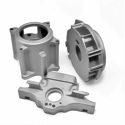
Structural design is fundamental to die-casting design. Ideally, the geometry should be determined based on the product’s function, avoiding complex structures that increase the difficulty of die-casting. First, castings should be symmetrical to minimize uneven stress during die-casting. For example, motor end covers should be designed with central symmetry to prevent deformation caused by cooling shrinkage. Second, avoid deep cavities and narrow gaps. Deep cavities (depth exceeding three times the diameter) can make filling with molten metal difficult, necessitating the addition of process holes or core pulls. Adding a core pull increases mold complexity by over 30%, requiring careful consideration during design. Narrow gaps (less than 1mm wide) can easily lead to under-casting and should be widened to 1.5-2mm or a step-by-step molding process should be employed. Furthermore, bosses and ribs on castings should be kept to a minimum height of twice their diameter, and rib thickness should be 0.6-0.8 times the thickness of the adjacent wall to prevent shrinkage. A company’s aluminum alloy housing design, due to a deep cavity, had a pass rate of only 60% on the first mold trial. After design modifications and the addition of process holes, the pass rate increased to 95%.
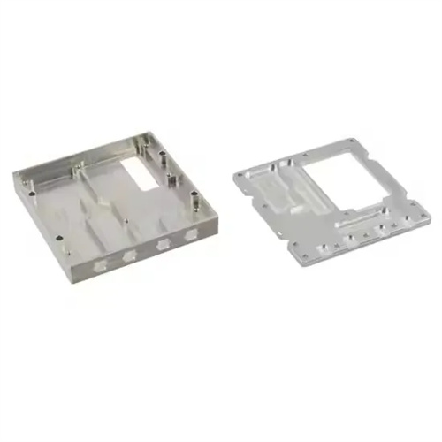
Wall thickness design is a critical parameter in die-casting design, ensuring smooth metal filling and uniform cooling of the casting. Excessive wall thickness can lead to defects such as shrinkage and porosity, while excessively thin walls can easily cause under-casting and cold shuts. The appropriate wall thickness range depends on the alloy type and casting size: zinc alloy die-castings typically have a wall thickness of 1-3mm, aluminum alloys 1.5-5mm, and copper alloys 2-6mm. Wall thickness variations within the same casting should be kept within 30% to avoid internal stresses caused by varying cooling rates. For example, a sudden increase in the wall thickness of a mobile phone’s midframe from 1.2mm to 3mm can cause severe deformation, necessitating a gradual transition. For thick sections (such as the base), hollowing out or reinforcing ribs can be used to reduce wall thickness while maintaining strength. For example, a hollow design for a machine base reduced the wall thickness from 5mm to 3mm, resulting in a 40% weight reduction without shrinkage defects. Wall thickness design also needs to consider the injection capacity of the die-casting machine. Thin-walled parts require a higher injection speed (8-10m/s). During design, it is necessary to confirm whether the equipment parameters match.
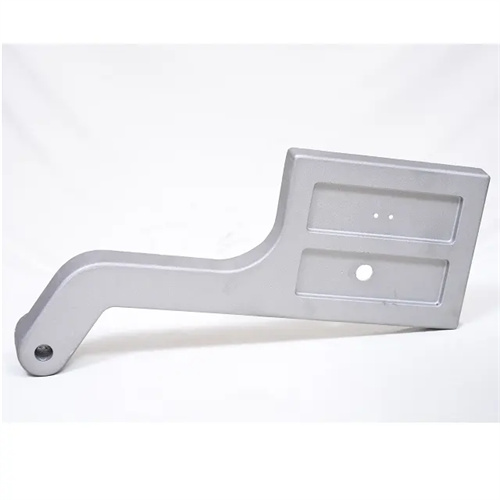
Corner fillets and transition designs can reduce stress concentration, improve the mechanical properties of die-cast parts, and enhance die life. All corners should be rounded to avoid sharp or sharp corners. The outer fillet radius is typically 0.5-1 times the wall thickness, while the inner fillet radius is the outer fillet radius plus the wall thickness. For example, for a 2mm-thick casting, the outer fillet radius should be 1-2mm, and the inner fillet radius should be 3-4mm. Transitions between flat and vertical surfaces should adopt a gentle slope (angle ≤ 30°) to avoid abrupt turns. For example, a 30° slope between the side and bottom of a box can reduce eddy currents and air entrainment during filling. The design of thread and tooth profiles should consider die-casting feasibility. Thread diameters should not be too small (those below M3 are prone to deformation), and the tooth module should be ≥ 0.8mm. Otherwise, subsequent machining is required. A die-cast gear frequently fractured during use due to a lack of tooth root fillet. After modifying the design and adding a 0.5mm fillet, the fatigue life increased threefold.
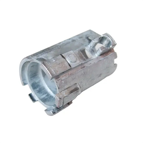
Designing the draft angle is crucial for ensuring smooth demolding of die-cast parts. The appropriate draft angle should be determined based on the casting’s height and surface roughness. The draft angle for the cavity (inner surface) is typically 0.5°-2°, and for the core (outer surface) it’s 0.3°-1°. The draft increases with height. For a 100mm tall casting, for example, the cavity draft should be ≥1.5°. For castings with low surface roughness (e.g., Ra ≤ 0.8μm), the draft angle can be reduced to avoid compromising fit accuracy. Castings with rougher surfaces should have a larger draft angle to prevent sticking. For surfaces with critical fits, the draft angle must be precisely calculated to ensure the assembly dimensions are within tolerance. For example, the draft angle for a bearing hole is set at 0.5°, with the maximum and minimum diameter deviations ensuring a consistent fit. A housing casting with an excessively small draft angle (0.2°) resulted in demolding difficulties and surface scratches. Increasing the draft angle to 0.8° allowed for smoother demolding and improved surface quality.
Mold adaptability design must consider the structural characteristics of the die-casting mold to ensure that the designed die-casting is easy to manufacture and operate. The gating system design must match the casting structure. The ingates should be located in thick areas of the casting to avoid direct impact with the core. For example, in box-type castings, the ingates should be located in thick areas on the side walls to reduce mold wear. The venting system design must ensure smooth evacuation of gases from the mold cavity. Vents with a depth of 0.05-0.1mm and a width of 5-10mm should be provided in the final filled area. For example, continuous venting grooves should be provided along the edges of cover-type castings. The ejector mechanism design should select an appropriate ejector location to avoid ejection marks that may affect the appearance. The ejector pins should have a diameter of ≥3mm and be evenly distributed. For example, the ejector pins on a mobile phone case are located on a non-exterior surface with a spacing of ≤50mm. In one mold, uneven ejector pin distribution caused deformation during ejection. By increasing the number of ejector pins, the deformation was reduced from 0.3mm to 0.1mm. In addition, the cooling system of the mold needs to be considered during design, and cooling water channels should be set up in thick and large parts to ensure uniform cooling and improve production efficiency.