Die casting ribs and holes
The ribs and holes in die-cast parts are crucial features for achieving structural functionality. Ribs enhance the rigidity and strength of the casting and reduce deformation, while holes facilitate assembly, weight reduction, and functional realization. The design of these ribs and holes must take into account the specific characteristics of the die-casting process to avoid structural inconsistencies that can lead to filling difficulties, mold complexity, or casting defects. A sound design can ensure performance while reducing production costs.
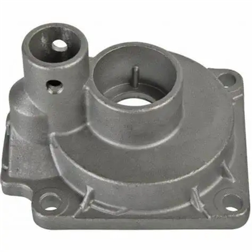
The rib design of die-cast parts must adhere to the principle of “fine and dense,” with its dimensional parameters closely related to the main body wall thickness. Rib thickness is typically 0.6-0.8 times the wall thickness of the connecting part. For example, for an aluminum alloy casting with a 3mm main body wall, the rib thickness should be 1.8-2.4mm. Excessive thickness can cause shrinkage at the rib-to-body connection, while too thin a rib will provide no reinforcement. Rib height should be limited, generally no more than five times the rib thickness. For example, a 2mm-thick rib should be within 10mm. Excessive height can easily lead to undercasting or bending deformation. The connection between the rib and the main body requires a transition radius of 0.5 times the rib thickness to reduce stress concentration. For example, a 2mm-thick rib should have a transition radius of 1mm. Ribs should be evenly and symmetrically distributed to enhance overall rigidity. For example, a rectangular shell should have cross ribs around the perimeter and center, spaced 50-100mm apart to prevent warping. The aluminum alloy cover produced by a certain factory had uneven rib distribution, resulting in a flatness error of 0.5mm after cooling. After redesigning it into a grid-like rib structure, the flatness was controlled within 0.1mm.
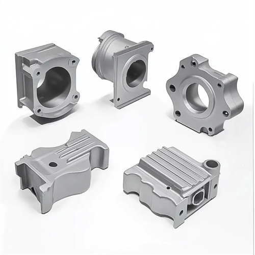
The structural form of ribs should be selected based on the stress characteristics of the casting. Common types include straight, diagonal, circular, and cross ribs. Straight ribs are simple to machine and are suitable for areas subject to unidirectional forces (such as the sides of a housing). Diagonal ribs (at an angle of 30°-45°) offer better torsional resistance and are suitable for components subject to torque (such as motor mounts). Circular ribs enhance the radial strength of circular components (such as gearboxes). Cross ribs (at 90° or 60° angles) offer optimal rigidity and are suitable for large, flat parts (such as machine tool worktops). For large, thin-walled parts (such as automotive floors), variable-section ribs, thick at the base and thin at the top, can be used to ensure strength while reducing weight. A new energy vehicle chassis casting using variable-section cross ribs achieves a 12% weight reduction and a 25% increase in rigidity compared to traditional straight ribs. Furthermore, the ends of the ribs should not protrude beyond the casting surface and should be set back 0.5-1mm to prevent burrs during demolding.
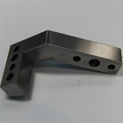
The hole design for die-cast parts must consider the forming method and subsequent processing requirements. Holes are categorized by forming method as either directly die-casting or post-processing. The diameter of directly die-casting holes should not be too small. The minimum formable diameter for zinc alloy is 1.5mm, 2mm for aluminum alloy, and 3mm for copper alloy. Excessively small hole diameters can easily cause the core to bend or break. The ratio of hole depth (length) to diameter is strictly limited: through holes should not exceed four times the diameter, and blind holes should not exceed three times the diameter. For example, a 5mm diameter through hole should have a depth of 20mm or less. Otherwise, the core will deform, affecting the hole’s verticality. The distance between the hole and the edge of the casting should be ≥ 1.5 times the hole diameter. For example, for a 5mm diameter hole, the edge distance should be ≥ 7.5mm to avoid edge cracking. For holes requiring subsequent processing (such as threaded holes), a machining allowance should be reserved during die-casting. The hole diameter should be 1-2mm smaller than the final size. For example, for an M10 threaded hole, the die-cast hole diameter should be 8.5-9mm to ensure a defect-free hole wall after processing. The aluminum alloy connectors of a certain factory had a blind hole with a depth-to-diameter ratio of 5 times, which resulted in core bending and excessive hole verticality. The accuracy was met after the depth was shortened.
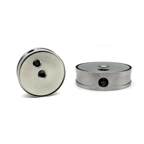
The location and distribution of holes significantly impact casting quality. Avoid holes that are too densely packed or too close to the edges of the casting. The distance between holes should be ≥ 1.5 times the average diameter of the two holes. For example, for two 6mm diameter holes, the spacing should be ≥ 9mm to prevent insufficient strength or cracking in the area between the holes. If the distance between the holes and the casting edge is insufficient, a boss can be added to increase wall thickness. The boss diameter should be 2-3 times the hole diameter and the height should be 0.5-1 times the hole diameter. For example, for a 5mm hole, the boss diameter should be 10-15mm and the height should be 2.5-5mm. The design of inclined holes (non-perpendicular to the parting line) requires consideration of core pulling mechanisms. Inclined core pulling can be used for angles ≤ 15°. Larger angles require hydraulic core pulling, which increases mold cost. Therefore, the angle of inclined holes should be kept within 30°. Because a box casting was designed with a 45° inclined hole, the mold had to use hydraulic core pulling, which increased the cost by 30%. After changing to a 20° inclined hole, mechanical core pulling was used, which reduced the cost.
The design of ribs and holes must match the mold structure to minimize mold complexity and machining difficulty. Rib design should avoid excessive metal buildup at intersections. This can be achieved by staggering the ribs or by providing process holes at the intersections. For example, the thickness of the intersection of cross-ribs should not exceed 1.5 times the thickness of the main body wall, otherwise shrinkage may occur. Hole cores should be integral whenever possible to minimize joints and improve strength. For example, for holes under 10 mm in diameter, the core can be machined from solid round steel. For larger holes, a composite core can be used, but coaxiality must be ensured. For deep holes or holes in complex locations, a cooling system should be installed in the mold to prevent core overheating and metal sticking. For example, for holes 20 mm deep, cooling water channels should be installed within the core, with the water temperature controlled between 50 and 80°C. In a mold, the lack of cooling for the deep-hole core resulted in overheating, metal sticking, and unacceptable hole wall roughness. Adding cooling was required to resolve the issue. In addition, the design of the ribs and holes must facilitate mold exhaust. Exhaust grooves are set at the end of the ribs and the bottom of the holes to ensure that the gas in the cavity is discharged smoothly.