Die casting surface shape and tolerance
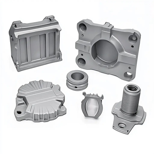
The surface shape and tolerance of die-cast parts are crucial parameters for ensuring product assembly performance and functional realization. Surface shape includes flat surfaces, curved surfaces, threads, and tooth profiles, while tolerances represent the allowable range of dimensional variation. Together, these two factors determine the interchangeability and reliability of die-cast parts. Properly designing surface shape and tolerances not only meets product requirements but also reduces production costs and improves efficiency.
The surface design of die-cast parts must be integrated with product functionality and the specific characteristics of the die-casting process to avoid complex surfaces that are difficult to form. Flat surfaces are the most common surface shape, and their flatness must be ensured during design. Large flat surfaces (over 200mm x 200mm) require reinforcing ribs to prevent deformation, and beveled or rounded edges should be provided to facilitate metal filling and demolding. Curved surfaces must maintain a uniform radius of curvature and avoid sharp changes. For example, the transition radius of curved surfaces on automotive panels should be ≥5mm, otherwise wrinkles or dents may occur. When die-casting complex surfaces such as threads and tooth profiles, both mold processing difficulty and part release properties must be considered. The thread diameter should not be too small (subsequent machining is recommended for diameters below M3). The tooth profile module should be ≥1mm, and a sufficient draft angle (≥1°) should be provided. A gear die-casting with a designed module of 0.8mm exhibited low tooth profile accuracy after die-casting. Changing the module to 1mm and increasing the draft angle improved the tooth profile accuracy by two levels. In addition, the depth of structures such as bosses and grooves on the surface must not exceed twice the width, otherwise insufficient filling or mold wear may occur.
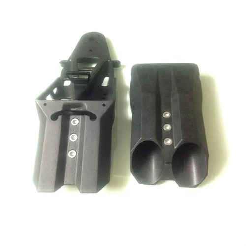
Dimensional tolerances must be determined based on the product’s assembly requirements and die-casting process capabilities. They should be neither too tight, which increases production costs, nor too loose, which can affect assembly performance. Dimensional tolerances for die-cast parts are typically based on GB/T 18514-2001, “Technical Specifications for Die-Casting Die Parts,” or ISO 8062. Zinc alloy die-castings can achieve tolerances of IT11-IT13, aluminum alloys IT12-IT14, and copper alloys IT13-IT15. For mating parts (such as shaft-hole fits), tolerances must be strictly controlled. For example, for a sliding fit, the hole tolerance is H8, and the shaft tolerance is f7; for a fixed fit, the hole tolerance is H7, and the shaft tolerance is k6. Tolerances for non-mating parts can be relaxed appropriately. For example, a ±0.5mm tolerance on the outer contour of a box can meet requirements. The aluminum alloy connectors produced by a certain factory had a pass rate of only 70% because the mating hole tolerance was set to H7 (+0.015/0), which could not be achieved by the die-casting process. After relaxing the tolerance to H8 (+0.022/0), the pass rate increased to 95%.
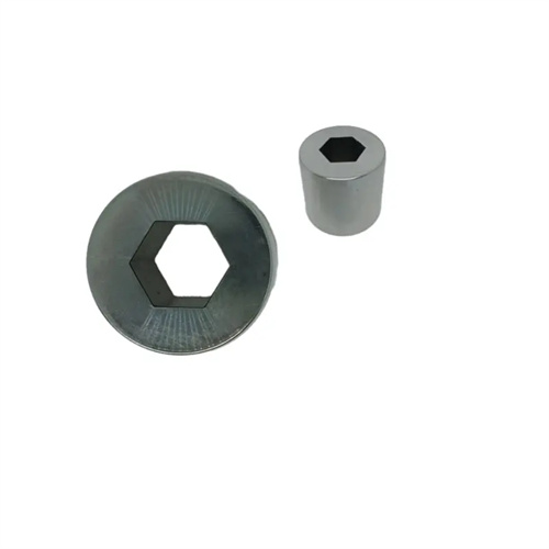
Form tolerances include straightness, flatness, roundness, and cylindricity. Controlling form tolerances ensures the proper fit and smooth movement of die-cast parts. Excessive flatness errors can lead to poor sealing. For example, the sealing surface of a hydraulic valve body must have a flatness of ≤0.05 mm/m, otherwise leakage will occur. Excessive roundness errors can affect the rotational accuracy of shaft parts. For example, the roundness of a motor shaft must be ≤0.01 mm. The size of the form tolerance depends on the size of the casting. The flatness of small castings is typically ≤0.1 mm/m, while that of large castings is ≤0.2 mm/m. The roundness tolerance is approximately 1/2-1/3 of the dimensional tolerance. For example, for a 50 mm diameter hole, the dimensional tolerance is ±0.03 mm, while the roundness tolerance is set at 0.01-0.015 mm. A hydraulic equipment manufacturer strictly controls the flatness of the valve body sealing surface (≤0.03 mm/m). By optimizing the mold cooling system and adding aging treatment, they have increased the sealing pass rate from 85% to 99%.
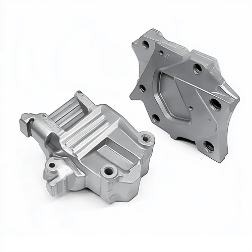
Positional tolerances, including parallelism, perpendicularity, coaxiality, and positional accuracy, ensure the relative positional accuracy between various elements of a casting and are crucial for smooth assembly. Parallelism errors can lead to uneven force distribution after part assembly. For example, the parallelism between the guideway surface and the reference surface must be ≤0.1mm/m; otherwise, motion resistance increases. Perpendicularity errors can affect transmission accuracy. For example, the perpendicularity between the gear shaft and the end face must be ≤0.05mm/m. For areas with high coaxiality requirements (such as stepped holes), tolerances are typically set to φ0.05-φ0.1mm. For example, the coaxiality between the bearing hole and the stopper in a motor end cap must be ≤φ0.05mm; otherwise, bearing wear increases. Positional tolerances are determined based on assembly requirements. For example, a positional tolerance of ±0.1mm for mounting holes ensures smooth bolt assembly. A certain automobile transmission housing experienced gear meshing problems due to excessive coaxiality (up to φ0.2mm) in the bearing hole. By improving the mold positioning structure, the coaxiality was controlled within φ0.08mm, resolving the meshing issue.
Control measures for the surface shape and tolerance of die-cast parts must be implemented throughout the entire design, mold manufacturing, and production process. During the design phase, CAD/CAE software is used for simulation analysis to predict potential shape and dimensional deviations and optimize the structure in advance. During the mold manufacturing phase, high-precision machining equipment is employed to ensure the mold’s shape and positional accuracy. For example, a three-dimensional coordinate measuring machine (CMM) is used to measure the accuracy of the mold cavity, and corrections are made if the error exceeds 0.01mm. During the production process, die-casting parameters (such as injection speed and mold temperature) are controlled to reduce shape and dimensional deviations. Castings are regularly sampled and inspected, and CMMs and shape measuring machines are used to monitor accuracy changes and adjust process parameters in a timely manner. A large die-casting company has established a comprehensive precision control system that monitors the entire process from design to production. This system has achieved a stable pass rate of die-casting dimensional tolerances above 98%, and a pass rate of 95% for shape and positional tolerances, significantly improving product competitiveness.