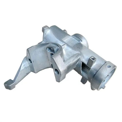
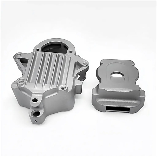
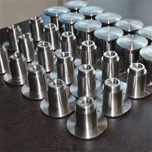
Die-cast inserts and removable cores for easy installation
The ease of installation of inserts and active cores in die-casting molds directly impacts mold assembly efficiency, maintenance costs, and production stability. Inserts, as crucial components of die-castings, enhance strength, conductivity, and functionality, while active cores are used to form complex features (such as side holes and grooves) on the casting. Improper installation design not only prolongs mold assembly time but can also lead to casting failures and even mold damage during production due to loosening or misalignment. Therefore, during the design phase, it is crucial to ensure simple and efficient installation of inserts and active cores through structural optimization, standardized interfaces, and the provision of positioning devices.
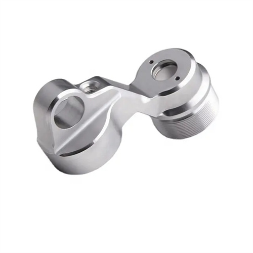
The installation design of the insert must take into account both positioning accuracy and ease of operation. First, the connection between the insert and the mold should adopt a standardized structure, such as cylindrical pin positioning, threaded connection or interference fit, to avoid complex non-standard interfaces that increase the difficulty of installation. For example, for cylindrical inserts, positioning holes with guide cones can be set at the corresponding positions of the mold. The angle of the guide cone should be 30°-45°, which can not only guide the insert to be inserted quickly, but also ensure the coaxiality after installation. At the same time, the installation height of the insert should be 0.1mm-0.2mm lower than the mold parting surface to prevent the insert from colliding with the opposite mold when the mold is closed. For inserts installed in batches, special installation tooling can also be designed, such as multi-station positioning plates, so that multiple inserts can be positioned at the same time, greatly shortening the installation time.
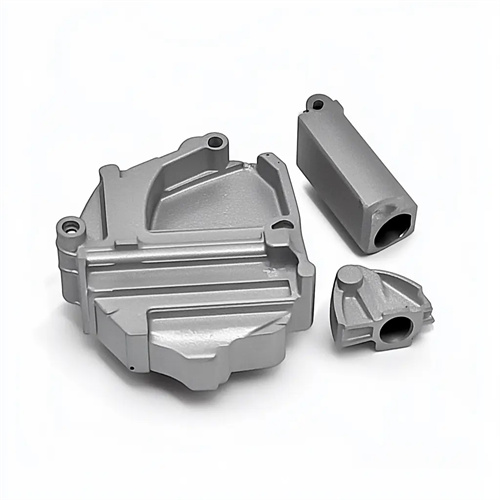
The installation structure of the movable core must meet the dual requirements of fast loading and unloading and precise positioning. The movable core is usually connected to a core-pulling mechanism (such as a hydraulic cylinder or inclined guide column), and its connection method should be easy to disassemble, such as using a keyway and bolt fastening, or a modular plug-in structure. In terms of positioning, the mating surface of the movable core and the template should be equipped with locating pins or guide keys to ensure that the position accuracy error of the core does not exceed 0.02mm after each installation. In addition, the installation space of the movable core must reserve sufficient operating clearance, generally not less than 20mm, to facilitate the operator to use tools for loading and unloading. For large movable cores, screw holes for lifting rings can also be set on the top to complete the installation with the help of lifting equipment, reducing the intensity of manual labor.
Guiding and foolproofing designs are key to ensuring the correct installation of inserts and movable cores. The entrance to the insert mounting hole can be chamfered or rounded to reduce bumps during installation. The mating area between the movable core and the mold plate can utilize a stepped guide, first using a large-clearance guide section for rapid alignment, then a small-clearance mating section to ensure precision. Foolproofing designs can prevent failures caused by incorrect installation orientation. For example, designing the insert or core cross-section with an asymmetrical shape (such as a D-shape or waist-shaped shape) or providing locating holes of different sizes on the mounting surface ensures that it can only be installed in a single orientation. These seemingly subtle features can significantly reduce assembly errors in actual production and improve mold reliability.
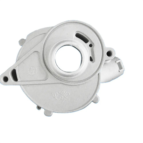
The tightening and detection mechanism after installation also affects the use effect. After the insert is installed, an anti-loosening structure, such as a spring washer, a stop washer or a thread sealant, must be used to prevent loosening due to vibration during the die-casting process. The connecting bolts between the movable core and the core pulling mechanism should be of high strength grade (such as grade 8.8 or above) and tightened according to the specified torque to avoid breakage after being subjected to force. After the installation is completed, the position of the insert and the movement accuracy of the movable core must be tested by measuring tools (such as a dial indicator, a three-coordinate measuring machine) to ensure that they meet the design requirements. For molds produced by automated production, sensors can also be installed at the installation location to monitor in real time whether the insert is installed in place to prevent production accidents caused by missing or incorrect installation.
Finally, ease of maintenance is also a factor to consider in installation design. Movable cores are susceptible to wear and tear over long periods of use, so their mounting structure should facilitate quick replacement. For example, the core could be designed as a removable insert, allowing replacement without disassembling the entire core-pulling mechanism. The mounting holes for the inserts should be easy to clean to prevent residual metal debris from affecting the accuracy of the next installation. Furthermore, the mold assembly drawings must clearly indicate the installation sequence, tightening torque, and testing requirements for the inserts and movable cores, providing clear guidance for operators. These measures ensure the installation accuracy of the inserts and movable cores, improve mold assembly efficiency, and enhance maintenance convenience, laying the foundation for stable operation of die-casting production.