Die casting mold core pulling force and core pulling distance
The core-pulling force and distance of a die-casting mold are two core parameters in the design of the core-pulling mechanism, directly determining the mechanism’s type, power configuration, and structural dimensions. The core-pulling force refers to the force required to extract the core from the casting, primarily composed of the casting’s grip on the core, friction, and the added resistance during core pulling. The core-pulling distance is the minimum distance the core must be pulled, ensuring that the core is completely free of the casting to avoid interference during demolding. Accurately determining these two parameters is essential for ensuring the reliable operation of the core-pulling mechanism. Excessively large parameters can easily lead to a bulky mechanism and increased costs, while too small parameters can make core pulling difficult or damage the casting.
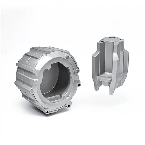
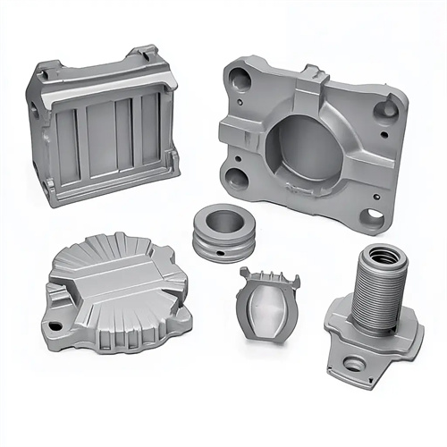
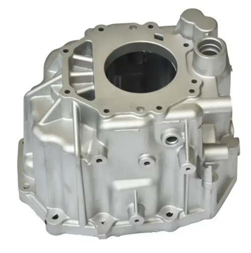
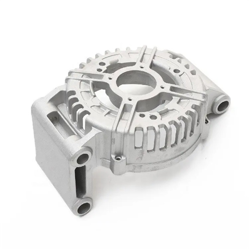
The magnitude of the core-pulling force primarily depends on the clamping force between the casting and the core, which is determined by the shrinkage characteristics of the molten metal, the surface area of the core, and its surface roughness. The molten metal shrinks during solidification, exerting a clamping force on the core. The greater the shrinkage (e.g., 1.2%-1.5% for aluminum alloys), the greater the clamping force. The larger the contact area between the core and the casting, the greater the clamping force. For example, the inner core of a large box-shaped casting requires a greater core-pulling force than the side core of a small bracket. Furthermore, higher core surface roughness increases friction with the casting, further increasing the core-pulling force. A safety factor (typically 1.5-2.0) should be factored in during actual calculations to account for uncertainties in the core-pulling process, such as increased resistance caused by casting deformation and residual coating.
The core pulling force is also affected by the structure of the casting and the direction of core pulling. When the core has a boss or groove perpendicular to the core pulling direction, additional tearing force will be generated, and the core pulling force needs to be increased accordingly; the greater the angle between the core pulling direction and the direction of demoulding of the casting, the greater the required core pulling force. Therefore, the core pulling direction should be consistent with the axis of the core as much as possible to reduce the influence of the component force. For alloys with a large thermal expansion coefficient (such as magnesium alloys), the clamping force of the casting on the core will increase significantly at high temperatures. The effect of temperature on the core pulling force needs to be considered during design, and heating or cooling should be used to assist core pulling when necessary. In addition, excessively fast core pulling speed will cause the core pulling force to increase instantaneously, and the core pulling speed needs to be controlled within a reasonable range (mechanical core pulling ≤ 50mm/s, hydraulic core pulling ≤ 100mm/s).
The core pulling distance should be determined based on the principle of ensuring the core is completely free of the casting. It is typically determined by adding a safety margin to the core’s maximum dimension in the pulling direction. For example, for side-hole castings, the core pulling distance should be 2-5mm greater than the depth of the side hole. For cores with steps, the core pulling distance should cover the maximum protrusion of the step, while adding a safety margin of 3-5mm to prevent scratching of the core during demolding. The core pulling distance also needs to account for the elastic deformation of the casting. For castings made of highly ductile aluminum alloys, the safety margin can be appropriately reduced. For brittle materials (such as zinc alloys), the safety margin should be increased to prevent scratches on the core due to slight deformation of the casting.
The core pulling distance is closely related to the type of core pulling mechanism. The core pulling distance of a mechanical core pulling mechanism is limited by the mold opening stroke. For example, the maximum distance of a slanted guide pin core pulling depends on the length and inclination angle of the slanted guide pin (usually ≤100mm). The core pulling distance of a hydraulic core pulling mechanism is determined by the hydraulic cylinder stroke and can be designed to be 200-500mm based on demand, but the mold installation space must be considered. In a multi-core core pulling mechanism, the core pulling distance of each core must be calculated separately, and it must be ensured that the core pulling actions do not interfere with each other. For example, pull out a short-distance core first, then a long-distance core, to avoid intersecting motion trajectories. The design of the core pulling distance must also be coordinated with the ejection mechanism to ensure that after the core pulling is completed, the ejection mechanism can smoothly eject the casting from the mold.