Settings of various parts of the push rod ejection mechanism of the die casting mold
The design of each component of the die-casting mold’s ejector mechanism must be carefully considered, taking into account the casting structure, material properties, and production process requirements. Scientifically and rationally designed layout and parameters ensure a stable and efficient demolding process. From the placement of the ejector pins to the positioning of the guides, each component’s configuration directly impacts the mold’s lifespan and casting quality, necessitating meticulous planning and verification.
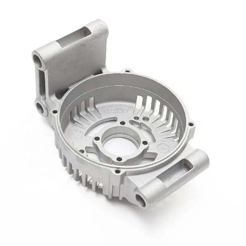
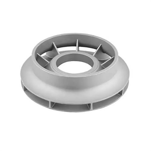
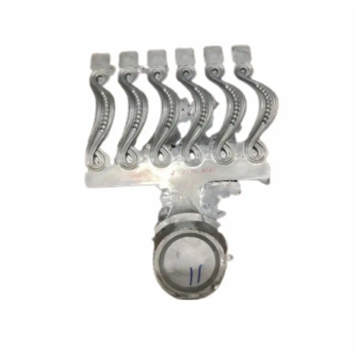
The setting of the push rod is the core of the ejection mechanism design. Its number, position and distribution need to be determined according to the stress conditions of the casting. For large-area flat-plate castings, the push rods should be evenly distributed on the edges or reinforcing ribs of the casting to avoid warping and deformation of the casting due to excessive local stress. Usually, the push rod spacing is controlled between 80-150mm. For castings with deep cavities or complex structures, push rods need to be added at the bottom or corners of the cavity. For example, push rods are set at the intersection of the ribs of the casting. This can not only enhance the thrust transmission effect, but also prevent the casting from tearing during ejection. In addition, the contact area between the push rod and the casting needs to be moderate. If it is too small, it will easily cause indentations on the casting surface, and if it is too large, it will increase the difficulty of push rod processing. The general contact diameter is 5-20mm, which needs to be calculated and determined based on the thickness of the casting and the strength of the material.
The setting of the push rod fixing plate and the push plate must meet the strength and rigidity requirements while ensuring assembly accuracy. The thickness of the fixing plate should be determined according to the number and distribution of push rods, usually 20-50mm. The material should be 45 steel or Cr12, and it has sufficient load-bearing capacity after quenching and tempering. The size of the push plate must match the mold movable die base plate, and a certain guide margin should be reserved on its edge to cooperate with the guide pillar and guide sleeve to achieve precise sliding. During assembly, locating pins must be installed between the push rod fixing plate and the push plate to ensure that the relative position of the two is fixed to avoid displacement caused by loosening of the screws due to long-term use, which affects the coaxiality of the push rod. In addition, a gap of 5-10mm should be reserved between the push plate and the movable die base plate for installing the reset spring and avoiding movement interference.
The setting of the guide pin and guide sleeve must ensure the smooth movement and guiding accuracy of the ejection mechanism. The length of the guide pin should be greater than the maximum ejection distance of the ejector plate, usually 20-30mm longer than the maximum ejection stroke, to ensure that the guide pin always cooperates with the guide sleeve during the ejection process. The installation position of the guide pin should be away from the area with dense ejector rods to avoid spatial interference with the ejector rods. It is generally arranged at the four corners or symmetrical sides of the ejector plate. The height of the guide sleeve needs to match the thickness of the ejector plate, usually slightly higher than the surface of the ejector plate by 1-2mm, to prevent the ejector plate from tilting during movement, which will cause increased wear on the guide sleeve. For large molds, auxiliary guide pins can be added to further improve the guiding stability. The diameter of the auxiliary guide pins is generally 1/2-2/3 of the main guide pins, and they are distributed between the main guide pins to form uniform support.
The reset device should be set up according to the degree of automation and production efficiency requirements of the mold, and the appropriate type should be selected. When using a reset spring, the specifications of the spring must be determined based on the total mass of the ejection mechanism and the reset force. The compression of the spring should be controlled between 30% and 50% of the free length to avoid elastic fatigue caused by excessive compression. The depth of the spring mounting hole must be 5-10mm larger than the free length of the spring to ensure that the spring can be fully extended during the reset process. For mechanisms that use a reset rod, the length of the reset rod must be accurately calculated to ensure that the push plate can be pushed to the initial position when the mold is closed. The top of the reset rod should be 0.1-0.2mm higher than the surface of the push plate to form a reliable reset force when in contact with the fixed mold. In addition, a wear-resistant gasket must be installed between the reset rod and the push rod fixing plate to reduce wear caused by long-term contact and extend the service life.
The setting of the limit and buffer device is an important guarantee for the safe operation of the ejection mechanism. The height of the limit pin should be set according to the maximum ejection distance, and the gap between its top and the push rod fixing plate is 0.1-0.2mm, which can not only limit the ejection stroke but also avoid rigid collision. In high-speed die-casting molds, a buffer pad, such as a polyurethane gasket or a spring washer, can be installed between the ejection plate and the movable mold base plate to use its elasticity to absorb the impact force at the end of the ejection and reduce component vibration and noise. For molds with a core pulling mechanism, the limit device must also form a linkage control with the core pulling action to ensure that the ejection action is carried out after the core pulling is completed to avoid mechanism interference. Timing control is usually achieved through a travel switch or a mechanical block.