Installation and positioning of die casting inserts in the mold
The installation and positioning of die-casting inserts within the mold are crucial for die-casting quality, directly impacting the bond strength between the insert and the die-cast part, as well as dimensional accuracy. The mounting structure must ensure the insert maintains a stable position in the high-temperature, high-pressure die-casting environment while facilitating quick replacement and maintenance. Positioning accuracy must be controlled within 0.05mm to avoid product scrapping due to insert misalignment. The design process must consider the insert’s material (e.g., steel, copper, plastic), shape (e.g., cylindrical, irregular), and functional requirements, selecting the appropriate mounting and positioning method, balancing reliability and cost-effectiveness.
The design of insert mounting structures must consider ease of installation and removal as well as connection strength. They are primarily categorized as removable and fixed. Removable mounting is suitable for inserts that require frequent replacement, enabling quick installation and removal through threaded connections, snap-fit mechanisms, or magnetic devices. Threaded connections utilize hexagon socket head cap screws or set screws. Screw sizes range from M3 to M8 , depending on the weight of the insert. Tightening torque is controlled between 5 and 30 N · m , ensuring a secure connection without damaging the insert. The snap-fit mechanism utilizes elastic claws that engage grooves in the insert. The claws are made of 65Mn spring steel, achieving a hardness of 40-45 HRC after heat treatment and a controlled deformation of 0.5-1mm . This ensures effortless installation and removal while providing sufficient clamping force. Magnetic devices are suitable for ferromagnetic inserts and utilize strong NdFeB magnets with a magnetic strength of 50-200N. Combined with locating pins, they secure the insert during mold closing, reducing replacement time to less than 30 seconds.
Fixed mounting is suitable for mass-produced standard inserts. The insert is secured to the mold locating element via an interference fit or welding. The interference fit is controlled to 0.01-0.03mm. The insert is cooled with liquid nitrogen and then pressed into the locating hole to ensure a strong bond. This method is suitable for installing cylindrical inserts. Laser welding or argon arc welding is used, with weld points 3-5mm in diameter and the number determined by the insert size. This ensures that the weld strength is no less than the tensile strength of the insert itself. This method is suitable for installing special-shaped inserts. The advantage of fixed mounting is high positioning accuracy (≤0.02mm). The disadvantage is that replacement is difficult. This method is suitable for mature products with long lifecycles, such as standard inserts for automotive chassis.
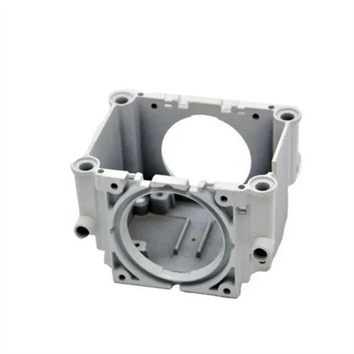
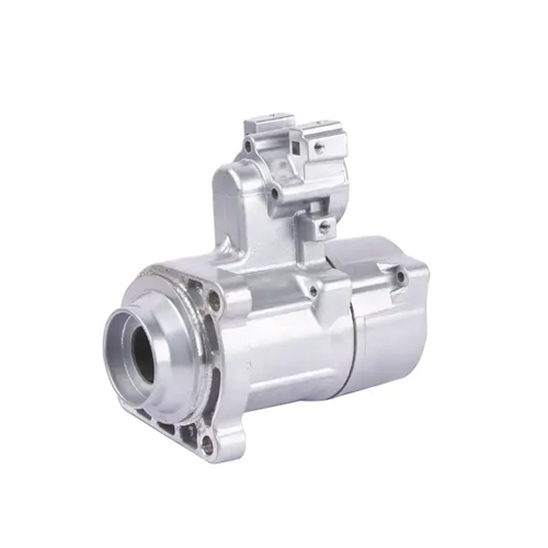
The selection of a positioning datum is fundamental to ensuring the accuracy of insert positioning and must be consistent with the die-casting design datum to achieve “datum unification.” For axisymmetric inserts, the axis and end face are used as datums, using a combination of double locating pins and annular steps for positioning. The clearance between the locating pin and the insert hole is 0.01-0.02mm, and the flatness error of the step surface is ≤0.01mm/100mm. For asymmetric inserts, at least two non-collinear positioning points are required, along with anti-rotation features such as keyways and flat keys. The key width tolerance is controlled to H7/h6 to prevent the insert from rotating during the die-casting process. The positioning datum surface must be precision machined to a surface roughness of Ra ≤0.8μm to avoid positioning errors caused by uneven datum surfaces. For example, when positioning a bearing insert in a motor housing, the insert’s outer diameter and end face are used as datums, combined with anti-rotation flattening, to ensure a coaxiality error of ≤0.03mm between the insert and the housing.
The positioning device must be designed to withstand the lateral and impact forces experienced during the die-casting process. The lateral force calculation formula is F = P × A (P is the specific pressure of the molten metal, typically 50-100 MPa; A is the lateral projected area of the insert). The positioning device’s load-bearing capacity must be 1.5-2 times the calculated value. The diameter of the positioning pin is determined based on shear force calculations using the formula d ≥ √(4F/(π[τ])), where [τ] is the material’s allowable shear stress (300 MPa for 45 steel). For example, when the lateral force is 10,000 N, the positioning pin diameter must be ≥ √(4×10,000/(3.14×300)) ≈ 6.5 mm. 8 mm is typically used. The positioning step should be at least 5 mm thick and made of quenched and tempered 40Cr steel (hardness 28-32 HRC). Finite element analysis has verified that deformation under load is ≤ 0.01 mm, ensuring uncompromised positioning accuracy.
Temperature compensation is a special requirement in high-temperature die-casting environments. Differences in the linear expansion coefficients of the insert and mold materials can cause variations in positioning clearance. For a copper insert (linear expansion coefficient of 17×10⁻⁶/ °C) and a steel mold (linear expansion coefficient of 11×10⁻⁶/ °C), at a die-casting temperature of 600 °C, the gap between a 100mm diameter insert and the mold varies by approximately 0.07mm . A temperature compensation gap of 0.05-0.1mm should be reserved during the design . Elastic positioning structures, such as wave springs, should also be employed to automatically adjust the preload force in response to temperature fluctuations. Furthermore, the positioning device should have a cooling water channel located 15-20mm from the positioning surface , with the water temperature controlled between 50-70 °C, to minimize the impact of temperature fluctuations on positioning accuracy. This temperature compensation design keeps the insert’s positioning error within 0.05mm over the entire temperature range, meeting high-precision die-casting requirements.