The feeding and positioning design of die-casting inserts is a core technology that ensures a reliable connection between the insert and the die-cast part. The quality of this design directly impacts the mechanical properties and dimensional accuracy of the product. As a metal or non-metallic part pre-installed in the mold, the insert must form a secure connection with the molten metal during the die-casting process. Therefore, the rationality of the feeding method and the level of positioning accuracy are crucial. The design process must comprehensively consider the insert’s material, shape, size, and production batch size, selecting an appropriate feeding system and positioning structure while balancing ease of operation and production efficiency to achieve high-quality, efficient insert die-casting production.
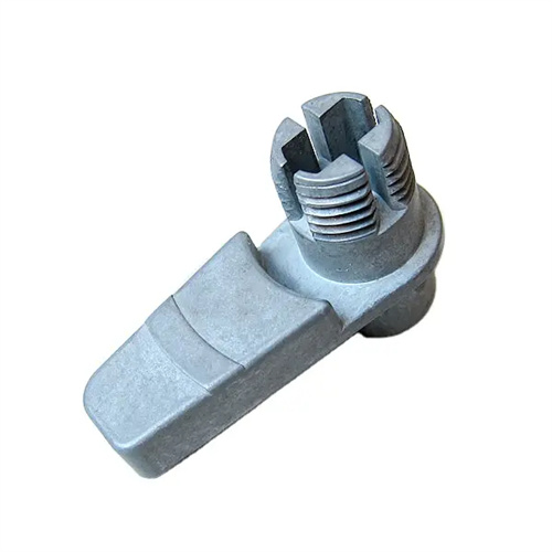
The design of the insert feeding system needs to be divided according to the production batch and the degree of automation, and is mainly divided into three categories: manual feeding, semi-automatic feeding, and fully automatic feeding. Manual feeding systems are suitable for small-batch production or large, special-shaped inserts. The core of the system is to design a pick-and-place structure that is easy for manual operation, such as a gripping boss on the insert or a dedicated tool. Manually fed molds must be equipped with safety guards on the operating side to avoid safety accidents caused by misoperation. At the same time, the positioning device must have clear guide markings, such as color markings or mechanical error-proofing structures, to ensure that the operator can quickly and accurately place the insert. For example, for large inserts weighing more than 5kg, auxiliary support mechanisms can be designed to reduce the intensity of manual handling and control the feeding time to 10-15 seconds per piece to meet the needs of small and medium-sized batch production.
Semi-automatic feeding systems combine manual operation with mechanical assistance and are suitable for medium-volume production. They typically consist of a vibrating feeder, an orienting mechanism, and a retrieving platform. The vibrating feeder arranges the inserts in an orderly manner through high-frequency vibration, the orienting mechanism ensures the correct insert posture through shape screening, and the retrieving platform separates the inserts individually for easy grasping by the operator. During design, the vibration parameters must be optimized according to the geometric characteristics of the inserts, with the amplitude controlled at 0.5-2mm and the frequency at 50-100Hz to prevent the inserts from getting stuck or becoming confused. For example, for cylindrical inserts with holes, the orienting mechanism can use notch screening, allowing only inserts with a vertical axis to pass. The orienting accuracy must reach above 99% to ensure feeding stability. The retrieving platform must be equipped with a sensor that sends a prompt signal when the insert is in place, shortening manual pick-up and placement time and keeping the single-piece feeding cycle within 5-8 seconds.
A fully automatic feeding system is the preferred solution for high-volume production. It primarily consists of a robotic gripper, a vision positioning system, and a conveyor track, enabling fully automated operations from feeding to installation. The robot must be equipped with an adaptive gripper, using either pneumatic fingers or vacuum suction cups depending on the insert’s shape. The gripping force is adjusted in real time via a pressure sensor to avoid surface damage. The vision positioning system utilizes a high-precision industrial camera with a resolution of at least 2 megapixels, coupled with image processing algorithms, to compensate for insert position deviations in real time, achieving a positioning accuracy of ±0.02mm. The conveyor track is driven by a servo motor, synchronized with the die-casting machine cycle, typically running 10-20 pieces/minute, meeting the demands of efficient production. For example, in the die-casting of inserts for automotive motor end caps, a fully automatic feeding system can achieve eight hours of continuous, hands-free production, maintaining an Overall Equipment Effectiveness (OEE) above 90%.
The design of the insert’s positioning structure must adhere to the “six-point positioning” principle. Strategically distributed positioning points constrain the insert’s six degrees of freedom, ensuring no displacement under die-casting pressure. Common positioning methods include pin-hole positioning, step-type positioning, and cavity-envelope positioning. Pin-hole positioning utilizes one or two positioning pins that mate with prefabricated holes in the insert, with a clearance of 0.01-0.03mm. This is suitable for inserts with holes. Step-type positioning utilizes an annular step on the mold to constrain axial movement. The step height is 0.1-0.2mm greater than the insert thickness, ensuring adequate coverage of the molten metal. Cavity-envelope positioning achieves positioning through precise alignment of the insert’s outer contour with the mold cavity, with a single-side clearance of 0.02-0.05mm. This is suitable for odd-shaped inserts. The positioning structure should be constructed of wear-resistant materials, such as quenched Cr12MoV (hardness 55-60 HRC), to prevent degradation of positioning accuracy over time.
The auxiliary design of the positioning system is equally important, including pre-tightening devices, anti-deformation structures and overflow control. The pre-tightening device uses a spring pressure plate or a magnetic suction cup to apply a pre-tightening force of 5-15N to the insert to prevent the insert from loosening during the mold closing process. The spring compression is controlled at 5-10mm to ensure the stability of the pre-tightening force. For thin-walled inserts, auxiliary supports such as distributed ejectors are required to avoid deformation of the inserts caused by die-casting pressure. The ejector diameter is 3-5mm, and the distribution density is not less than 1 per 100mm². Overflow control is achieved by setting a slag collecting groove around the positioning gap. The groove width is 3-5mm and the depth is 1-2mm to prevent the molten metal from penetrating the positioning fitting surface and affecting the removal of the insert. Through the above design, the positioning accuracy of the insert can be controlled within 0.05mm, and the deflection of the insert of the die-cast part does not exceed 0.1mm, meeting the requirements of high-precision products.