Die casting gears and mesh
The gears and mesh patterns of die-cast parts are surface features that combine precise functionality with complex structures. Gears, as transmission components, require guaranteed tooth profile accuracy and meshing performance, while mesh patterns play a key role in filtration, heat dissipation, and decorative applications. Die-casting of both requires stringent mold precision and process control. Design must balance transmission efficiency, flow performance, and manufacturing feasibility. During production, precise parameter control is required to achieve consistent quality and prevent product functionality from being compromised by tooth profile deviations or mesh clogging.
The core parameters of die-cast gear design must be determined based on transmission requirements. Module, a key indicator, must be selected according to load size. For light-load transmission (power ≤5kW), a range of 0.8-5mm is recommended. A module less than 0.8mm can lead to insufficient tooth profile fill, while a module greater than 5mm increases the risk of shrinkage. The number of teeth is calculated based on the transmission ratio. A 20° pressure angle is preferred for versatility. The addendum height coefficient is 1, and the top clearance coefficient is 0.25. For example, an aluminum alloy gear with a 2mm module and 20 teeth has a tip diameter of 44mm and a root diameter of 35.2mm. The precision grade is typically GB/T 10095 Grade 8-10, with a cumulative pitch error of ≤0.15mm and a tooth profile error of ≤0.05mm, meeting the requirements of applications such as toy motors and small transmission mechanisms. A motor gear at a toy factory was originally designed with a 0.6mm module. After die-casting, the tooth profile was blurred, resulting in high transmission noise. Switching to a 0.8mm module improved the precision to Grade 9 and reduced noise by 15 decibels.
The gear die-casting process requires key control over tooth profile filling and dimensional stability. Die tooth profiles are machined using slow-speed wire cutting or high-precision electrospark forming (EDM). A tooth surface roughness of Ra ≤ 0.8μm and a tooth profile accuracy of IT7 are achieved, ensuring smooth, burr-free castings. The injection pressure should be higher than for conventional castings—60-80 MPa for aluminum alloys and 40-60 MPa for zinc alloys—to ensure the molten metal fills the tooth root fillets. Extending the holding time by 20-30% can reduce tooth tip shrinkage. For one aluminum alloy gear, extending the holding time to 5 seconds reduced the tooth tip shrinkage from 8% to 1%. The mold should have dedicated cooling channels, with the water temperature near the tooth surface controlled at 40-60°C to prevent local overheating and ring gear deformation. On one gear, radial runout reached 0.1mm due to uneven cooling, but this was reduced to less than 0.05mm after optimized cooling. Furthermore, aging treatment (120°C/2h for aluminum alloys) is required after die-casting to eliminate internal stresses and stabilize dimensions.
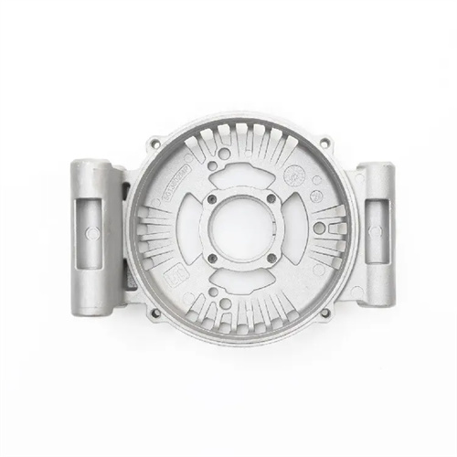
Mesh design should be structured according to function. Filtration meshes (such as hydraulic filters) utilize diamond or circular apertures with a diagonal of 5-10mm, an angle of 60°, and a wall thickness of 1-2mm, ensuring a flow efficiency of ≥90%. The diamond pattern of one hydraulic filter achieves a filtration accuracy of 20μm, meeting system cleanliness requirements. Heat dissipation meshes (such as motor end covers) utilize circular apertures with a diameter of 3-5mm and a spacing of 5-8mm. This increases surface area and improves heat dissipation efficiency. One motor end cover mesh increased heat dissipation by 40% and reduced operating temperature by 15°C. Decorative meshes utilize a fine grid or fish-scale pattern with a line width of 0.1-0.3mm and a spacing of 0.5-1mm. Laser processing mold cavities ensure uniform patterns. The grid pattern on appliance panels significantly enhances product quality.
Reticulated die casting requires addressing core strength and filling challenges. For hole diameters ≤3mm, a thin, small H13 steel core is used. Cores with diameters of 1-2mm require surface hardening (HRC 50-55) to prevent bending and fracture. A circular-hole patterned casting experienced bending after 500 cycles due to an unhardened core. After replacing the hardened core, the lifespan increased to 5,000 cycles. In densely populated areas (hole pitch ≤2mm), venting grooves 0.05-0.1mm deep are installed to prevent air from being trapped in the mesh and causing gaps. A certain square mesh pattern has seen its mesh integrity improved from 90% to 99% by enhancing venting. Deep mesh patterns (depth >2mm) require a 0.5-1° draft angle, combined with a dedicated ejection mechanism, to prevent edge damage during demolding. A diamond-shaped pattern with no draft experienced an edge damage rate of 12%, but this rate decreased to 1% after increasing the draft.
Gear and mesh quality testing requires specialized equipment and methods. Gears are tested using a gear measuring center for cumulative pitch error, profile deviation, and radial runout. A sample of 5-10 pieces is collected from each batch, with a pass rate of ≥95%. A transmission gear passed rigorous testing with a pitch error within 0.08mm and a transmission efficiency of 96%. An image measuring instrument is used to check for aperture and pitch deviation. Errors exceeding ±0.1mm require mold adjustment. The mesh blockage rate is also checked; if it exceeds 3%, the core needs cleaning. Functional testing involves testing gears for transmission efficiency and noise, while mesh is tested for flow and heat dissipation performance. Testing of an automotive oil pump gear revealed profile errors resulting in an efficiency of only 92%. This efficiency was improved to 96% after rework. A system of first-article inspection and regular spot checks ensures stable and controllable gear and mesh quality.