Die casting threads and inserts
The threads and inserts of die-cast parts are key components for achieving assembly functionality. Threads provide detachable connections, while inserts enhance local strength or enable the joining of dissimilar materials. The design of threads and inserts must consider the specificities of the die-casting process to ensure molding quality and connection reliability. Improper design can lead to problems such as thread stripping and insert loosening, compromising product performance.
The thread design for die-castings requires selecting the appropriate type and parameters based on the material properties and stress conditions. Commonly used threads include metric, imperial, and pipe threads. Zinc alloy die-castings have lower thread strength and are suitable for connections with light loads. Coarse threads in the M3-M10 range are recommended, with a pitch of 0.5-1.5mm and a thread depth no greater than 1.5 times the diameter. For example, for an M6 thread, the depth should be ≤9mm. Aluminum alloy threads offer higher strength and can be in the M2-M16 range. High-strength aluminum alloys like 6061 can withstand greater loads and have thread depths up to 2 times the diameter. Copper alloy threads offer the highest strength and are suitable for high-pressure sealing applications (such as hydraulic fittings). M8-M20 threads are commonly used and require use with sealant. The thread accuracy grade is typically 6H/6g, with a surface roughness of Ra ≤ 3.2μm to avoid surface roughness that can cause poor fit. A factory’s zinc alloy connectors used M2 fine threads, which frequently slipped during assembly. After switching to M3 coarse threads, the pass rate increased to 99%.
Directly die-cast threads have limitations, and quality assurance measures are required. One or two incomplete threads are required at the thread’s beginning to prevent flash at the top of the thread. An undercut groove is required at the end, with a width of 1-1.5 times the pitch and a depth of 0.1-0.2 times the major diameter. For example, for a 1mm pitch thread, the undercut groove should be 1-1.5mm wide and 0.3-0.5mm deep. The minimum diameter of internal threads should be 3mm or greater, and for external threads 2mm or greater. Threads that are too small are difficult to die-cast and can easily damage the mold core. For threads requiring high precision (e.g., clearance ≤0.05mm), tapping or threading after die-casting is recommended. For example, the positioning threads in automotive transmissions can achieve 6H precision by pre-drilling the die before tapping. The internal threads of aluminum alloy on an aviation component require 5H precision, but the pass rate for direct die-casting was only 75%. By switching to die-casting the die before tapping, the pass rate reached 99%.
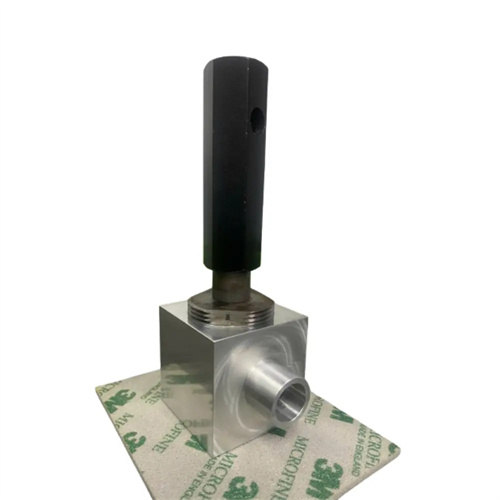
The design of die-cast inserts must ensure a good bond with the molten metal to prevent loosening or dislodging during use. The choice of insert material must consider compatibility with the die-cast alloy. Steel inserts bond well with aluminum and zinc alloys and are the most commonly used insert material. Copper inserts are suitable for die-casting with copper alloys. Plastic inserts, due to their poor heat resistance, are only suitable for low-temperature die-casting of zinc alloys. The surface treatment of the insert is crucial to bond strength. Steel inserts require galvanizing or phosphating to increase surface roughness (Ra12.5-Ra25μm), or knurling or grooves can be added to enhance mechanical engagement. For example, a 0.5mm deep annular groove on a 10mm diameter steel insert can increase bond strength by 40%. The insert wall thickness should be uniform to avoid excessive thickness, which can cause shrinkage during die-casting. Steel inserts typically have a wall thickness of 1-3mm. Large inserts can be provided with process holes to reduce weight. The aluminum alloy shell of a certain factory had a smooth steel insert surface, resulting in insufficient bonding strength. After the surface was changed to a knurled surface, the insert tensile force increased from 500N to 1200N.
The insert’s structure and installation method must facilitate die-casting operations and ensure accurate positioning. The insert’s length should be minimal, generally no longer than three times its diameter. For example, an 8mm diameter insert should be ≤24mm long. Excessive length can easily lead to deflection during die-casting. Inserts should have rounded corners (radius 0.5-1mm) on both ends to prevent sharp corners from scratching the mold or casting. For castings with multiple inserts, the distance between inserts should be ≥10mm, and the distance from the casting edge should be ≥5mm to prevent obstruction of molten metal flow during die-casting. Inserts should be installed using a positioning mechanism to ensure a positioning tolerance of ≤0.1mm. For example, positioning pins can be installed in the mold, positioning holes can be made in the insert, and the clearance should be 0.02-0.05mm. In the case of an automotive motor end cap, the coaxiality exceeded the tolerance by 0.3mm due to inaccurate insert positioning. After improving the positioning mechanism, the coaxiality was controlled within 0.05mm. In addition, the inserts need to be preheated to 150-200°C (steel inserts) to avoid cracks in the castings due to a sudden drop in temperature during die casting.
Quality control of threads and inserts must be implemented throughout the entire design, production, and inspection process. During the design phase, finite element analysis is used to verify the stress state of the threads and ensure that strength meets requirements. For example, ANSYS is used to analyze the stress distribution of an M8 thread under a tensile force of 1000N to avoid stress concentration. The integration process between the insert and the molten metal is simulated to optimize the insert structure. During the production phase, die-casting parameters for the threads, such as mold temperature and injection speed, are strictly controlled to ensure clear and complete threads. Before insert installation, surface treatment quality and dimensional accuracy are inspected, and after die-casting, inserts are checked for looseness (e.g., using a torque wrench). During the inspection phase, thread gauges are used to check thread accuracy, coordinate measuring machines are used to verify insert position, and tensile testing machines are used to test insert bonding strength. One company established a dedicated inspection process for threads and inserts, which increased the thread acceptance rate from 90% to 98% and reduced the insert looseness rate from 5% to 0.5%, significantly improving product reliability.