Die casting mold design program
Die-casting mold design is a systematic project that requires adherence to standardized design procedures to ensure quality. From product analysis to mold acceptance, each step has clear tasks and outputs. Oversights in any step can lead to mold scrapping or production failures. A scientific design process improves efficiency and reduces rework. It typically includes five phases: product process analysis, preliminary design, detailed design, simulation verification, and manufacturing acceptance. Each phase is interconnected, forming a closed-loop management system.
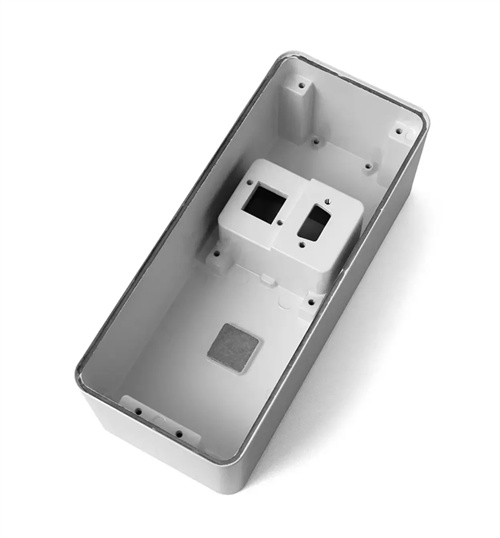
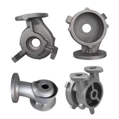
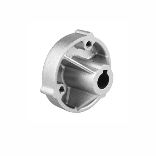
Product process analysis is the starting point of design. This requires a comprehensive interpretation of product drawings and an assessment of die-casting feasibility. First, the structural rationality of the die-cast part is reviewed, checking for issues such as excessively thin walls (<1mm), excessively deep cavities (depth > 3 times the diameter), or sharp corners (R < 0.5mm). For one housing, due to a 0.8mm thin wall, the customer was advised to modify it to 1.2mm to ensure fill. The casting's dimensional accuracy and surface quality requirements are analyzed to determine whether further machining is required. For precision levels above IT11, a machining allowance of 0.3-0.5mm is required. Surfaces with Ra ≤ 1.6μm require mold polishing to Ra ≤ 0.8μm. Die-casting process parameter ranges are determined based on the alloy type (zinc, aluminum, or copper). For example, for aluminum alloys, a specific injection pressure of 30-80MPa and a mold temperature of 200-250°C are recommended. Finally, a "Product Process Analysis Report" is produced, clarifying key design points and precautions. In one project, this detailed analysis identified three structural issues in advance, avoiding rework after mold fabrication.
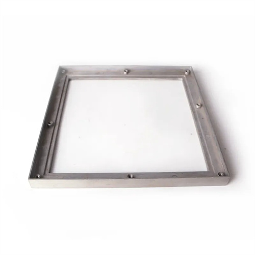
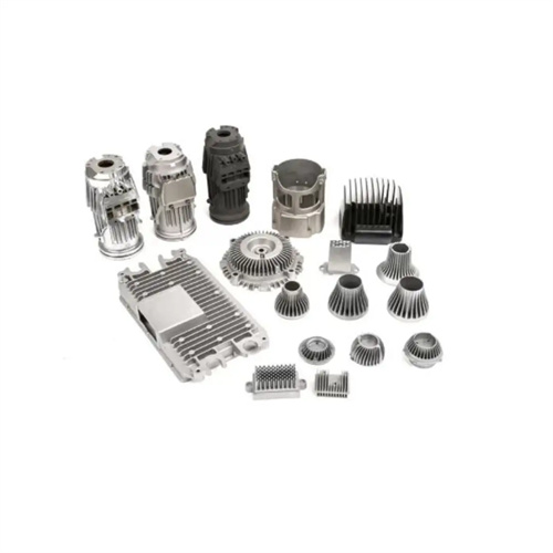
The preliminary design phase requires determining the overall mold design, including the number of cavities, parting surface location, and core pulling method. The number of cavities is determined by the production batch and the tonnage of the die-casting machine. For an annual production of 500,000 aluminum alloy parts, four cavities are used, while for 200,000 parts, two cavities are used. One company selected an appropriate number of cavities based on order volume, achieving an 85% equipment utilization rate. Parting surface selection prioritizes mold simplification and casting accuracy, with the largest cross-section of the casting being the preferred location. For one cover, locating the parting surface mid-plane reduces the need for one core pulling mechanism compared to placing it at the edge. The core pulling solution should evaluate the applicability of both mechanical (inclined guide pin) and hydraulic core pulling. Mechanical core pulling is used for core pulling distances <50 mm, while hydraulic core pulling is used for core pulling distances >50 mm. A hydraulic core pulling solution was used for the 80 mm core pulling distance of one housing to ensure stable operation. The preliminary design also requires the selection of the mold base. A standard mold base (such as the Longji LKM series) is selected according to the cavity size, and a “Preliminary Design Plan” and 3D layout drawing are output. A mold passed the preliminary design review and optimized two unreasonable structures.
The detailed design phase, which is a core step in the design process, requires the completion of 3D modeling and 2D engineering drawings for all parts. The cavity and core must be precisely modeled, with dimensional tolerances adjusted to the casting’s shrinkage requirements and surface roughness clearly marked. For one mold, the cavity is marked with Ra 0.8μm to ensure polishing accuracy. The core-pulling mechanism design requires calculation of the core-pulling force (F = K × A × p, where K is the coefficient, A is the projected area, and p is the unit pressure) and the core-pulling distance (5-10mm longer than required). For one core-pulling mechanism, the calculated force is 50kN, and a 63mm diameter hydraulic cylinder is used. For the ejector mechanism, the number and distribution of ejector pins must be determined to ensure uniform ejection force. Pin diameters should be ≥ 3mm and spacing ≤ 50mm. One cover plate design uses 12 ejector pins, eliminating ejector deformation. The cooling system requires a detailed waterway diagram, noting the diameter (8-12mm), distance from the cavity surface (15-25mm), and inlet and outlet locations. For one mold, the cooling waterway design ensures a cavity temperature difference of ≤ 5°C. Finally, a complete set of 3D models and 2D drawings, including the parts list (BOM), are output to ensure manufacturing accuracy.
During the simulation verification phase, CAE software was used to simulate the die-casting process, identifying design flaws in advance. Filling simulations analyzed the flow trajectory of the molten metal to check for underfilling, eddy currents, or air entrapment. For one mold, simulations revealed uneven filling due to improper gate placement, which was corrected after adjustments. Solidification simulations predicted the location of shrinkage and voids, leading to the addition of cooling or overflow channels in thicker areas. Simulations revealed central shrinkage in one thick-walled part, which was resolved after the addition of cooling channels. Stress analysis assessed mold deformation under clamping forces to ensure sufficient strength. Analysis of one large mold revealed mold frame deformation of 0.2mm, which was reduced to 0.05mm after thickening the mold plate. Simulations also verified the coordination of core pulling and ejection to avoid interference. Simulations revealed conflict between core pulling and ejection in one mold, which was resolved after adjusting the order. A simulation analysis report was generated, and the design was optimized based on the results. For one project, simulations increased the mold trial pass rate from 60% to 90%.
During the manufacturing acceptance phase, mold processing quality must be monitored and trial molds must be conducted to ensure compliance with design requirements. Key components (cavities and cores) undergo three inspections during the manufacturing process: after rough machining (dimensional tolerance ±0.1mm), semi-finishing (±0.05mm), and finishing (±0.01mm). A 0.02mm error was detected in one cavity after finishing, and rework resulted in compliance. After mold assembly, the mold is inspected for parting surface fit (clearance ≤ 0.01mm), guide pin and sleeve fit (clearance 0.01-0.02mm), and core pull flexibility. In one mold, core pull jammed due to overtightening, but became smooth after adjustment. During the trial mold, filling conditions, casting defects, and process parameters are recorded, and a “Mold Trial Report” is generated. In one mold, flash was detected during the trial mold, but the mold passed the test after adjusting the clamping force. Finally, a small-batch production run (50-100 pieces) is conducted to verify dimensional stability and mold life. Once qualified, the mold is released for use and passes acceptance, meeting the customer’s mass production requirements.