Manufacturability of die casting design
The manufacturability of die-casting design refers to the degree of compatibility between the design and the die-casting process. Good manufacturability reduces production difficulty, minimizes defects, and improves efficiency. Poor manufacturability, on the other hand, leads to mold complexity, increased costs, and inconsistent quality. Manufacturability design must be integrated throughout the entire product lifecycle . From material selection and structural optimization to dimensional tolerance determination, every step must consider the characteristics of the die-casting process, such as molten metal fluidity, solidification characteristics, and mold limitations, to achieve a balance between functionality and manufacturing.
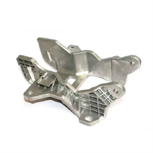
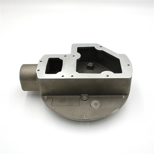
The manufacturability of material selection is reflected in the alloy’s adaptability for die-casting. Different alloys exhibit significant variations in fluidity, shrinkage, and formability, directly impacting the difficulty of the process. Zinc alloys (such as ZZnAl4Cu1) offer excellent fluidity and low shrinkage (0.5-1%), making them suitable for complex thin-walled parts (wall thickness 0.8-2mm). They also feature low die-casting temperatures (400-450°C) and a long mold life (up to 1 million cycles). They are among the most manufacturable die-casting alloys and are widely used in toys and household appliance parts. Aluminum alloys (such as ADC12) offer moderate fluidity and a shrinkage of 1-1.5%, making them suitable for structural parts of moderate complexity (wall thickness 1.5-5mm). Die-casting temperatures range from 650-700°C, with a mold life of 500,000-800,000 cycles. However, care should be taken to prevent oxidation and shrinkage. Copper alloys (such as ZCuZn38) have poor fluidity, a shrinkage rate of 1.5-2%, high die-casting temperatures (850-900°C), and short mold life (100,000-300,000 cycles). They are only suitable for simple, thick-walled parts (2-6mm thick) and exhibit the worst processability. One company originally planned to die-cast a complex valve body using copper alloy. However, due to the difficulty and high cost of the process, they switched to aluminum alloy with surface treatment, reducing production costs by 40% and increasing the pass rate to 95%.
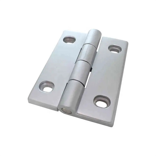
Manufacturability in structural design must adhere to the principles of “simplified shape, uniform wall thickness, and smooth transitions” to avoid complex structures that increase mold difficulty and lead to die-casting defects. Complex castings (such as those with multiple cavities or deep holes) require a process parting surface to separate the monolithic part into die-castable components, which are then assembled through welding or bolting. For example, a certain automobile transmission housing was originally designed as a monolithic structure, requiring 12 core-pulling mechanisms in the mold. Switching to three separate components simplified the mold structure and reduced costs by 30%. Wall thickness uniformity is crucial for manufacturability. The wall thickness difference within the same casting should be ≤30%, otherwise shrinkage and deformation are likely to occur. For example, an aluminum alloy cover plate experienced a 20% shrinkage rate due to a sudden increase in wall thickness from 2mm to 5mm. This shrinkage rate was reduced to 2% after switching to a gradual wall thickness (2-3.5mm). Rounded corners (radius ≥ 0.5mm) and slopes (angle ≤ 30°) are required at structural transitions to avoid eddy currents and stress concentration in the molten metal caused by right angles. After the right-angle transition of a certain box was changed to a 30° slope, the porosity defects were reduced by 60%.
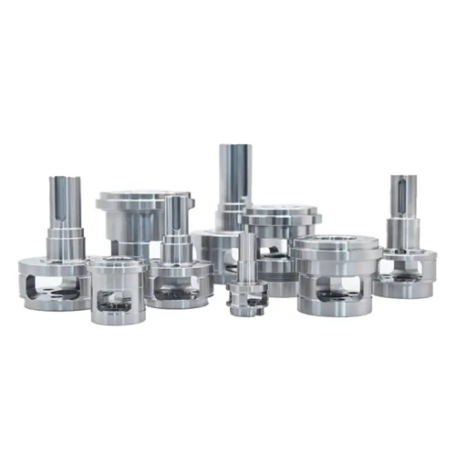
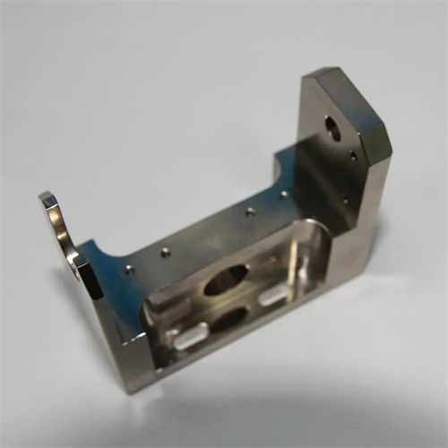
The processability of mold release and core pulling directly impacts mold complexity and production efficiency. The number and complexity of core pulling mechanisms should be minimized. Axial core pulling (perpendicular to the parting line) offers superior processability to oblique core pulling. The angle of oblique core pulling should be ≤ 30°. A larger angle increases the complexity and cost of the core pulling mechanism. For one casting, changing the 45° oblique hole to a 30° angle reduced core pulling mechanism costs by 50%. The core pulling distance should be ≤ 1/3 of the length of the corresponding part of the casting. Excessive length can lead to instability of the core pulling mechanism. For example, for a 100mm long boss, the core pulling distance should be kept within 30mm. For closed structures that cannot be core pulled (such as annular grooves), modular molds or soluble cores are required. For one annular part, salt core die casting is used, which dissolves after molding, solving the molding problem of closed grooves. Furthermore, internal concave structures should be avoided, as these require complex internal core pulling. For one shell, the internal concave was changed to an external convex, eliminating two sets of internal core pulling mechanisms in the mold and improving production efficiency by 15%.
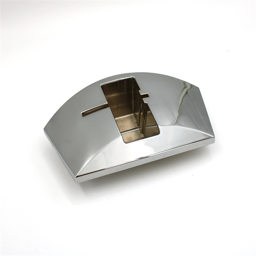
The processability design for dimensional tolerances and surface quality must be within the capabilities of the die-casting process to avoid excessively high requirements that lead to increased costs. The dimensional tolerances of die-cast parts are affected by factors such as alloy shrinkage fluctuations and die wear. Zinc alloys can reach IT11-IT13, aluminum alloys IT12-IT14, and copper alloys IT13-IT15. Tolerances must be determined accordingly during design. For example, the original design tolerance for an aluminum alloy bearing bore was IT10 (±0.02mm), resulting in a die-casting pass rate of only 70%. After relaxing the tolerance to IT12 (±0.05mm), the pass rate reached 98%. Regarding surface roughness, the Ra value of directly die-cast parts is typically 1.6-6.3μm. For decorative surfaces requiring an Ra ≤ 1.6μm, die polishing (Ra ≤ 0.8μm) is required, increasing costs by 10-20%. If subsequent processing (such as sandblasting and polishing) is permitted, the die-casting surface requirements can be lowered. A certain home appliance panel uses a die-casting + anodizing process to transform the surface of Ra3.2μm into Ra0.8μm, which not only meets the appearance requirements but also saves costs compared to direct die-casting of mirror surfaces.
Manufacturability verification and continuous improvement are crucial steps in ensuring design feasibility. Manufacturability assessment requires prototyping and mold trials. Prototyping can rapidly produce samples using 3D printing to verify structural rationality. For a complex casting, three locations where core extraction was impossible were discovered during prototyping, allowing for preemptive design modifications to avoid mold rework. During mold trials, it is important to record filling conditions, defect types, and production efficiency, and assess the design’s manufacturability score (e.g., mold complexity, pass rate, and cycle time). One casting scored only 65 after mold trials, but this score improved to 90 by optimizing rib distribution and wall thickness. Establishing manufacturability design guidelines to standardize material selection, structural parameters, and tolerance requirements is crucial. One company’s “Die Casting Manufacturability Design Manual” has reduced new product development cycles by 20% and mold modification rates by 30%. Furthermore, by strengthening collaboration between design and process departments and adopting a DFM (Design for Manufacturing) approach, process personnel are invited to participate in design reviews early in the design phase to identify manufacturability issues and achieve a seamless transition between design and manufacturing.