Design of overflow groove of die casting mold
The overflow chute design of a die-casting mold is a crucial element. Its primary function is to collect cold material, oxide slag, and entrained gases from the molten metal, preventing these impurities from entering the mold cavity and causing casting defects. It also regulates the flow of molten metal, compensates for shrinkage, and extends the life of the mold. The overflow chute design must be determined based on a comprehensive consideration of factors such as the casting’s structural shape, size, material properties, and die-casting process parameters. A reasonable design can significantly improve the quality and pass rate of die-casting parts while reducing production costs.
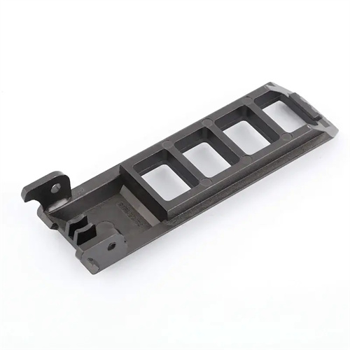
The location of the overflow chute is a primary design consideration, as its proper placement directly impacts slag collection and venting. Generally speaking, overflow chutes should be located near the last area of molten metal to be filled, such as the end of the cavity, corners, and dead zones, as these areas are prone to gas and cold material accumulation. For example, for castings with deep cavities, the overflow chute should be located at the bottom or top of the cavity to ensure that it can collect the molten metal and gas that are finally filled in this area. For complex frame castings, overflow chutes should be located at various corners to prevent eddy currents and gas accumulation caused by poor molten metal flow. Furthermore, overflow chutes should be located near critical areas of the casting, such as machined surfaces and stress-bearing surfaces, to ensure quality in these areas. When determining the overflow chute’s location, the mold’s structure and ease of operation must also be considered to avoid interference with ejection mechanisms, core pulling mechanisms, and other mechanisms, while facilitating subsequent cleaning and maintenance.
The shape and dimensions of the overflow chute must meet the requirements for slag collection, air venting, and shrinkage feeding. Common overflow chute shapes include rectangular, circular, triangular, and fan-shaped. Rectangular overflow chute is the most widely used, being easy to manufacture and providing excellent slag collection, making it suitable for most castings. Circular overflow chute offers a larger volume and better shrinkage feeding, making it suitable for thick-walled castings. Fan-shaped overflow chute better adapts to the mold cavity shape and is suitable for special-shaped castings. The overflow chute dimensions are determined by the volume of the casting and the flow rate of the molten metal. Generally, the length of the overflow chute ranges from 10mm to 50mm, the width from 8mm to 30mm, and the height from 5mm to 20mm. The overflow chute volume should be sufficient to accommodate the cold material and air, typically 5% to 15% of the casting volume. For large and complex castings, the volume can be increased appropriately. The connecting seam between the overflow chute and the mold cavity should be 3mm to 8mm wide and 0.5mm to 2mm thick, allowing for easy entry of the molten metal while creating a certain back pressure to ensure efficient filling of the cavity.
The structural design of the overflow chute must consider the flow characteristics of the molten metal and ease of demolding. A guide ramp with a slope of 15°-30° should be installed at the inlet of the overflow chute to facilitate smooth flow of molten metal. Baffles or bosses can be installed internally to redirect the flow of the molten metal, improve slag collection, and degassing. The bottom of the overflow chute should be designed with an inclined surface with a slope of 5°-10° to facilitate the demolding of the solidified material after solidification. For large overflow chutes, an ejector hole can be installed at the bottom to facilitate ejection of the solidified material during demolding. The sidewalls of the overflow chute should have an appropriate demolding slope, generally 1°-3°, to reduce demolding resistance. Furthermore, the surface roughness of the overflow chute should be controlled below Ra1.6μm to reduce frictional resistance to the flow of molten metal and facilitate cleaning.
The coordinated design of the overflow trough and the vent groove is the key to improving the overflow discharge effect. The overflow trough should be closely connected to the vent groove so that the gas collected in the overflow trough can be smoothly discharged to the outside of the mold through the vent groove. The vent groove is usually set at the end of the overflow trough, with a width of 10mm-20mm, a depth of 0.02mm-0.05mm, and a length not exceeding 50mm. The connection between the overflow trough and the vent groove should adopt a smooth transition, avoiding right angles or sharp turns to reduce the resistance to gas discharge. During the design, the size and number of the vent grooves should be reasonably determined according to the flow rate of the molten metal and the amount of gas generated to ensure that the gas can be discharged in a timely manner. For high-speed die-casting processes, the number and width of the vent grooves can be appropriately increased to improve the exhaust efficiency.
The design of the overflow trough must also consider the cooling and strength requirements of the mold. Cooling water channels should be installed around the overflow trough to control its operating temperature and avoid slow solidification of the molten metal due to excessively high temperatures, which would affect slag collection and exhaust. The distance between the cooling water channel and the overflow trough should be controlled at 15mm-25mm, and the water flow rate should be 1m/s-2m/s to ensure uniform cooling. The setting of the overflow trough should not affect the overall strength of the mold. The connection between it and the cavity should have sufficient thickness, generally not less than 10mm, to prevent deformation or damage to the mold due to excessive pressure during the die-casting process. For large overflow troughs, reinforcing ribs can be installed around them to enhance the rigidity of the mold. By comprehensively considering the above factors, it is possible to design an efficient and reliable overflow trough that fully plays its important role in die-casting production and improves the quality and production efficiency of die-cast parts.