The composition and function of the die casting mold overflow system
The die-casting mold overflow system is an essential component of the die. Its primary function is to remove gas from the mold cavity and store impurities and cold material in the molten metal, thereby improving the quality and yield of die-cast parts. The overflow system is a complex system consisting of an overflow trough, exhaust trough, slag collection bag, and corresponding connecting channels. These components work together to perform functions such as exhaust, slag collection, and shrinkage feeding. A properly designed overflow system can effectively reduce defects such as porosity, shrinkage cavities, and inclusions in castings, improve molten metal filling efficiency, and extend the life of the mold. It is a key factor in ensuring smooth die-casting production.
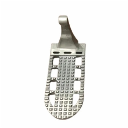
The overflow chute is a core component of the overflow system, typically located at the final point of molten metal filling, at the corners of the mold cavity, and in areas prone to eddy currents and gas accumulation. Its primary function is to contain the cold molten metal, slag, and entrained gases within the mold cavity, preventing these impurities from entering the casting and causing defects. The overflow chute’s volume is generally 5%-15% of the casting’s volume, with the specific size determined by the casting’s structure and dimensions. For example, for large, complex castings, the overflow chute’s volume can be increased to ensure adequate capacity for impurities and gases; for small, simple castings, the overflow chute’s volume can be reduced to minimize molten metal waste. The overflow chute is typically rectangular or circular in shape and connected to the mold cavity by a narrow slit, typically 3mm-8mm wide. This slit facilitates molten metal entry while creating a certain backpressure to ensure efficient cavity filling.
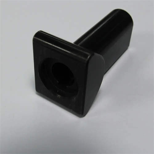
The vent groove is a key component of the overflow system, used to expel gas from the mold cavity. It is typically connected to the overflow chute or located directly on the parting surface. Its primary function is to promptly expel air, gases generated by paint volatilization, and gases contained in the molten metal during the molten metal filling process, preventing these gases from being trapped and forming pores within the casting. The depth and width of the vent groove are determined by the casting material and die-casting process parameters. For aluminum alloy castings, the vent groove depth is generally 0.02mm-0.05mm and the width is 10mm-20mm. For zinc alloy castings, the depth can be reduced to 0.01mm-0.03mm. The vent groove length should ensure smooth exhaust of gases, generally not exceeding 50mm. Excessive length increases gas discharge resistance. When designing the vent groove, care should be taken to avoid interference with other mold components and ensure easy cleaning to prevent clogging of the vent groove after solidification of the molten metal.
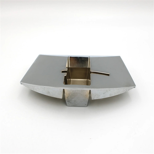
The slag collection bag is a component of the overflow system specifically designed to collect slag and impurities from the molten metal. It is typically located at the end of the overflow trough or at a bend in the molten metal flow. Its primary function is to leverage the flow inertia of the molten metal to draw less dense slag and impurities into the bag, preventing them from entering the mold cavity and impacting casting quality. The slag collection bag’s volume is generally 30%-50% of the overflow trough’s volume. It is typically spherical or cylindrical in shape, and may be equipped with internal baffles or filters to further enhance slag collection. The connecting channel between the slag collection bag and the overflow trough should be designed with an inclined slope of 5°-10° to facilitate the smooth flow of slag and impurities into the bag. During the die-casting process, impurities within the slag collection bag need to be regularly cleaned to ensure its continued effective slag collection capabilities.
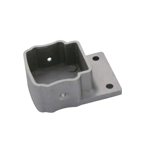
The connecting channel of the overflow system is a key component that connects the overflow trough, exhaust trough, and slag collection bag into a single integrated unit. Its design quality directly impacts the efficiency of the overflow system. The connecting channel’s cross-section is typically rectangular or trapezoidal, and its dimensions are determined based on flow requirements to ensure smooth flow of molten metal and gas. Corners in the connecting channel should be rounded, with a radius of at least 5mm, to avoid pressure loss and eddy currents caused by right-angle turns. The connecting channel’s length should be minimized to minimize flow resistance from gases and impurities. Furthermore, the surface roughness of the connecting channel should be controlled below Ra1.6μm to reduce frictional resistance to molten metal flow and facilitate demolding and cleaning. Properly designed connecting channels enable the various components of the overflow system to work together, fully utilizing their functions for exhaust, slag collection, and shrinkage feeding, thereby improving the quality and production efficiency of die-cast parts.