Design of the core-pulling mechanism of the die-casting mold
The design of the core-pulling mechanism in die-casting molds is crucial for ensuring the smooth molding of complex castings. Its primary function is to remove lateral, internal, or irregularly shaped cores that could hinder demolding before the mold is opened, ensuring the casting can smoothly exit the mold. The core-pulling mechanism must balance operational reliability, structural compactness, and cost-effectiveness, while also meeting the casting’s dimensional accuracy and surface quality requirements. The design process comprehensively considers factors such as core-pulling force, core-pulling distance, core structure, mold space, and production batch size. Selecting the appropriate mechanism and optimizing its parameters ensures efficient and stable production.
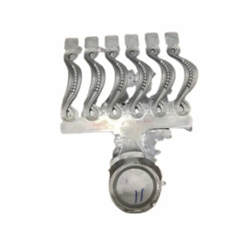
The selection of the type of core pulling mechanism is the first step in the design and needs to be determined based on the structural characteristics of the casting and the core pulling requirements. For castings with simple side holes or shallow undercuts, the inclined guide pin core pulling mechanism is an economical and practical choice. It uses the mold opening force to drive the core pulling, does not require an additional power source, has a simple structure and reliable operation. When the core pulling force is large (over 10kN) or the core pulling distance is long (over 100mm), a hydraulic core pulling mechanism is more suitable. It can provide stable power through the hydraulic cylinder, and the core pulling speed and stroke can be flexibly adjusted. For castings with threads, the rack and pinion core pulling mechanism can achieve rotary core pulling to ensure thread accuracy; for deep cavities or complex cores with limited space, the bent pin core pulling mechanism can avoid interference through broken line motion to achieve core pulling with complex trajectories. The type selection needs to be combined with production cost and production efficiency. Mechanical core pulling is given priority for small and medium-sized batch production, while hydraulic core pulling is more suitable for large-scale automated production.
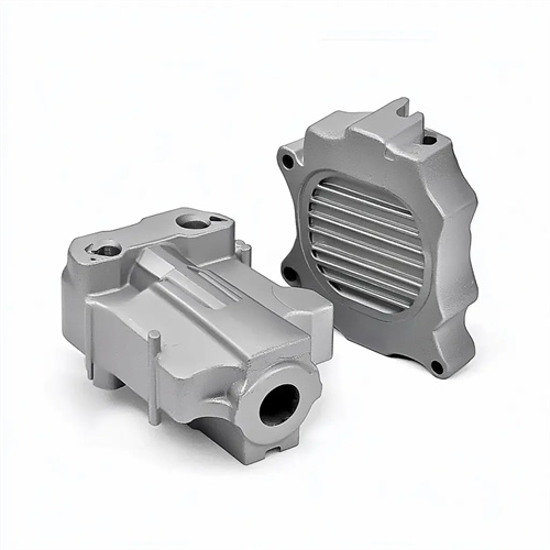
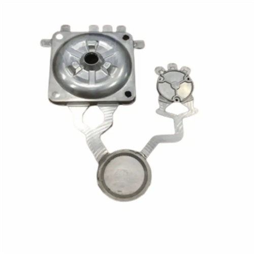
The structural design of the core directly affects the performance of the core-pulling mechanism and must meet molding requirements and ease of extraction. The working surface of the core should have sufficient smoothness (Ra≤0.8μm) to reduce friction with the casting during core pulling; the cross-sectional shape of the core should be as symmetrical as possible to avoid unbalanced loading during core pulling; for slender cores, additional reinforcing ribs or guide supports are required to prevent bending and deformation during core pulling. The contact area between the core and the casting must be reasonably controlled. If it is too large, it will easily lead to increased clamping force, while if it is too small, it may affect the molding accuracy of the casting. In addition, the root of the core should be designed with a rounded transition to avoid stress concentration, and sufficient installation space should be reserved to facilitate connection with the transmission components of the core-pulling mechanism.
The motion coordination design of the core pulling mechanism is extremely important, and it is necessary to ensure that the core pulling action is connected with the mold opening and ejection actions in an orderly manner. The core pulling start time of the core pulling mechanism should be earlier than the mold opening action to avoid the casting being damaged due to the core not being pulled out; after the core pulling is completed, the core must be completely separated from the casting, and the core pulling mechanism must be reset before the mold is closed to ensure the accurate position of the core during the next die casting. For hydraulic core pulling mechanisms, the end points of the core pulling and reset strokes must be controlled by travel switches or position sensors to ensure motion accuracy; for mechanical core pulling mechanisms, reliable positioning devices (such as positioning pins, springs) must be designed to prevent the core from being displaced due to vibration after core pulling. Motion coordination also needs to consider the opening and closing speed of the mold to ensure that the core pulling speed matches the mold opening speed to avoid impact loads.
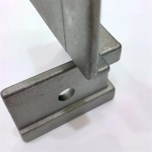
The strength and rigidity design of the core-pulling mechanism are key to ensuring its service life. Transmission components (such as inclined guide pillars, gears, and piston rods) must be strength-checked to ensure they can withstand the maximum loads during the core-pulling process. They are typically made of 45 steel or alloy structural steel and tempered or quenched (hardness ≥ 40 HRC). Guide components (such as sliders and guide grooves) must ensure sufficient fit accuracy (clearance 0.02mm-0.05mm) and be made of wear-resistant materials (such as bronze or wear-resistant cast iron) to reduce wear from long-term movement. The locking mechanism (such as the wedge block) must be able to withstand the molten metal pressure during die-casting. Its locking force should be 1.5-2 times the core-pulling force to prevent the core from retreating during the die-casting process. For large core-pulling mechanisms, finite element analysis is required to optimize the structural force distribution and avoid premature failure caused by excessive local stress.
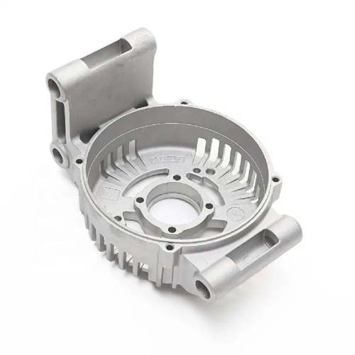
The ease of installation and debugging of the core-pulling mechanism must also be taken into consideration during design. The various components of the mechanism should be easy to disassemble and replace, and wearing parts such as sliders and guide pins should be designed as standard parts to reduce maintenance costs. A 5-10mm margin should be reserved for the core-pulling stroke to avoid insufficient core pulling due to installation errors. The spatial layout of the core-pulling mechanism and other mold components (such as the ejection mechanism and cooling system) must be reasonable to avoid interference. During the debugging process, the core-pulling position needs to be fine-tuned by adjusting gaskets or adjusting screws to ensure the accuracy of the fit between the core and the cavity. For hydraulic core-pulling mechanisms, the pressure and flow of the hydraulic system need to be adjusted to match the core-pulling speed with the mold opening speed. Exhaust issues must also be considered during design. Exhaust grooves should be set in the movement gap of the core-pulling mechanism to prevent air blockage from affecting the smoothness of the core-pulling action.