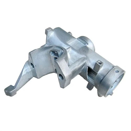
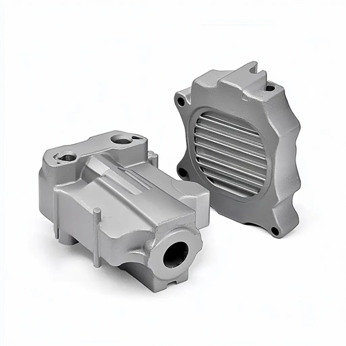
The shape of the ejection end of the die casting mold push rod
The shape design of the ejector tip of a die-casting mold requires comprehensive consideration of the casting’s structural characteristics, surface quality requirements, and demolding challenges. By optimizing the tip profile and dimensions, smooth demolding is achieved while minimizing damage to the casting surface. Different casting shapes and material properties correspond to different ejector tip designs. Common shapes include flat top, spherical, conical, and other special shapes, each with its own application scenarios and design considerations.
The flat-top ejector tip is the most commonly used design. Its end face is perpendicular to the axis of the push rod, making it easy to machine and providing a large contact area. It’s suitable for flat castings or applications where surface roughness requirements are low. The edges of the flat-top ejector tip are typically rounded with a radius of 0.5-1mm to avoid scratching the casting surface or causing stress concentration during the ejection process. During design, the diameter of the flat top should be determined based on the thickness of the casting, generally 1-1.5 times the push rod diameter. For thinner castings (less than 3mm thick), the flat top diameter can be reduced to prevent denting during ejection. Furthermore, the contact area between the flat-top ejector tip and the casting should avoid the exterior or mating surfaces of the casting. If this is not possible, the push rod end face should be polished to a surface roughness of less than Ra0.8μm to ensure the casting’s surface quality is not compromised.
The spherical ejector has excellent adaptability. Its end is a spherical surface with a radius of 5-20mm, making it suitable for curved castings or situations where there are slight deviations in the demolding direction. Spherical contact can reduce the rigid impact between the push rod and the casting, disperse the thrust through point contact, and avoid indentations on the casting surface. When designing the spherical radius, it must match the curvature of the casting surface. For concave castings, the spherical radius should be slightly smaller than the casting surface radius to ensure that the contact point is located at the center of the surface. For convex castings, the spherical radius should be slightly larger than the casting surface radius to form a reliable thrust transmission. The machining accuracy requirements for the spherical ejector are high, and the spherical profile must be controlled within 0.02mm. After nitriding, the surface hardness can reach HRC55 or above to improve wear resistance and service life.
Conical push-out tips are suitable for castings with holes or cylindrical structures. Their tapered ends, typically with an angle of 30°-60°, provide a certain degree of centering during the push-out process, preventing deflection due to uneven force. The height of the cone is determined by the hole diameter, generally 1/3-1/2 of the diameter. For holes with a diameter less than 10mm, the cone height can be reduced to avoid insufficient strength due to the rod’s thin end. Because the contact area between the push-out tip and the casting hole wall is small, a step is required at the base of the push-out tip to enhance its overall rigidity. The step diameter is 2-5mm larger than the diameter of the larger end of the cone, and the step height is 3-5mm. Furthermore, the surface roughness of the cone must be controlled below Ra1.6μm to prevent scratching the hole wall during push-out, which could affect the casting’s fit.
Special-shaped ejector tips are specially designed for complex castings. These include contoured tips that match the casting’s contours and hooked tips with grooves. They are suitable for thin-walled parts, deep-cavity parts, or castings with undercut structures. The shape of the contoured push rod’s end is identical to the local contour of the casting, maximizing the contact area and preventing deformation of thin-walled castings during ejection. For example, in automotive engine block die-casting molds, push rods for thin-walled areas such as the water jacket often adopt a contoured design. Hooked push rods are suitable for castings with internal undercuts. The grooves on their ends can hook onto the edge of the casting, providing upward pulling force during ejection, and working together with other push rods to complete the demolding action. The machining of special-shaped ejector tips requires precision machining methods such as electrospark forming or wire cutting to ensure that the shape accuracy perfectly matches the casting. At the same time, strength verification is required to avoid fracture caused by stress concentration due to the complex shape.
The shape design of the push rod’s ejection end also needs to consider the demolding angle and lubrication conditions. Regardless of the shape used, the area where the ejection end contacts the casting should be set with a demolding angle of 0.5°-1° to reduce frictional resistance during ejection. For materials that are prone to mold sticking, such as aluminum alloys, the angle can be appropriately increased to 1°-2°. In terms of lubrication, for high-temperature alloy castings, an annular oil groove can be opened at the end of the push rod to store high-temperature grease and reduce wear at high temperatures. For precision castings, if the use of lubricants is not allowed, the surface finish of the ejection end needs to be improved to achieve smooth demolding by reducing the friction coefficient. In addition, the size of the push rod’s ejection end needs to match the cavity gap. Generally, a gap of 0.05-0.1mm is reserved to prevent the push rod from colliding with the cavity during mold closing, and to prevent the metal liquid from seeping into the gap to form flash during the die-casting process.