Die-casting molded parts structure
Die-casting mold components are the core components that directly determine the shape, size, and surface quality of die-cast parts. These components include the cavity, core, and mold inserts. The selection of their structural form requires comprehensive consideration of factors such as the die-casting’s structural characteristics, material properties, production batch size, and mold manufacturing process. A reasonable structural form not only ensures die-casting molding quality but also improves mold life and production efficiency, reducing manufacturing costs.

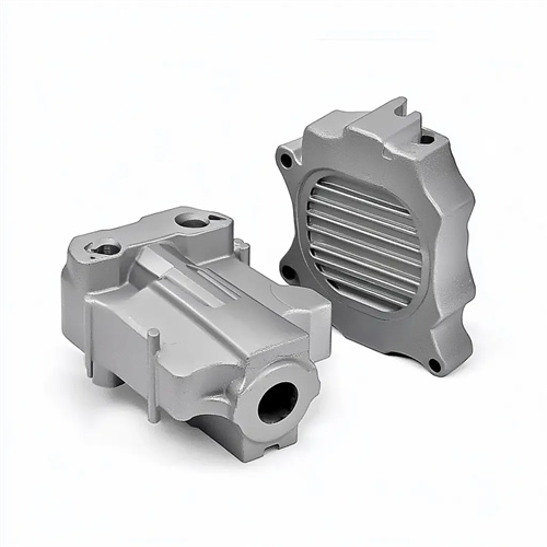
The monolithic structure is the most basic form of die casting, where the cavity or core and the mold plate are integrated into a single unit. The desired shape is machined directly onto the mold plate through processes such as forging, milling, and grinding. This structure offers advantages such as excellent rigidity, high strength, and the absence of joint gaps. It is suitable for simple, small-sized die castings, such as small gears and connectors. Monolithic cavities are typically manufactured from pre-hardened P20 or 718H steel, achieving hardnesses of up to HRC 30-35. This eliminates the need for subsequent heat treatment and reduces the risk of deformation during machining. However, for complex or large parts, the monolithic structure increases machining difficulty and material consumption. Partial wear or damage requires complete mold plate replacement, resulting in high maintenance costs.
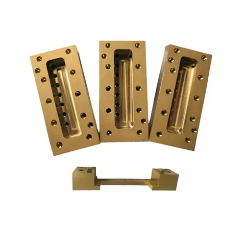
A modular structure breaks down the molded part into multiple modules, which are then assembled into a complete cavity or core through splicing or inlaying. This is suitable for die-casting parts with complex shapes, large dimensions, or special molding requirements. For example, for die-casting parts with deep cavities, complex patterns, or irregularly shaped holes, the cavity can be divided into a main insert, a side core insert, and a bottom insert, which are then processed separately and assembled into a complete unit. The modular structure offers the advantages of ease of processing and maintenance. In the event of local damage, only the corresponding insert needs to be replaced, reducing mold maintenance costs. Furthermore, inserts in different locations can be made of different materials based on operating conditions. For example, H13 hot-working die steel (HRC 45-50 hardness) can be used for the cavity surface to improve wear resistance, while 45 steel can be used for non-molding areas to reduce costs. However, the modular structure requires high assembly precision, ensuring that the coaxiality, parallelism, and flatness errors between the inserts are within 0.01mm to avoid flash or steps on the die-casting surface caused by splicing gaps.
The inlay structure is a special form of modular structure, primarily used for forming complex local structures on die-cast parts, such as threads, tooth profiles, and bosses. This localized forming is achieved by inserting specialized molding inserts into the mold cavity or core. Inlay inserts are typically manufactured from high-speed steel or carbide. After precision machining and heat treatment, they possess extremely high hardness and wear resistance, making them suitable for mass production or for forming high-hardness die-casting parts (such as aluminum and magnesium alloys). For example, when die-casting threaded parts, a threaded molding insert can be embedded into the core. The insert and core are secured with an interference fit or threaded connection to prevent loosening during the high-pressure die-casting process. The advantage of the inlay structure is its high degree of specificity, which can significantly extend the life of the localized molding area. However, the insert requires high positioning accuracy, using pins or stoppers to ensure that the relative position error with the main part does not exceed 0.005mm.
The spliced structure is suitable for the molding of large or extra-long die-cast parts, such as automobile body frames and large pipes. It is formed by splicing the mold cavity or core along the length or circumference. The spliced surface is usually designed with a stepped or dovetail shape to enhance the overall rigidity after splicing, and locating pins are provided to ensure the splicing accuracy. The advantage of the spliced structure is that it reduces the processing difficulty of large parts, facilitates the use of small and medium-sized processing equipment to manufacture large molded parts, and also facilitates heat dissipation from the mold, reducing deformation of the molded part caused by uneven temperature distribution. However, a sealing structure is required at the spliced joint, such as an overflow groove on the spliced surface, to prevent molten metal from overflowing from the gap and forming flash. The material selection for the spliced structure should be determined according to the stress conditions. High-strength alloy steel should be used in areas subject to greater stress, while ordinary structural steel can be used in less critical areas to reduce costs.
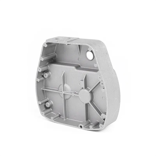
The structural design of the molded part also needs to consider exhaust and cooling requirements. During structural design, venting slots should be appropriately positioned within the cavity and core to ensure the smooth escape of gases generated during the die-casting process, preventing defects such as porosity and shrinkage in the die-casting. For modular or inlaid structures, the gaps between inserts can be utilized as exhaust channels, simplifying the mold structure and improving exhaust efficiency. Furthermore, the structure of the molded part should facilitate the installation of cooling water channels, such as spiral or circular channels at the bottom of the cavity or within the core. This ensures uniform temperature distribution during operation and minimizes thermal deformation. For example, for a monolithic cavity, straight or stepped water channels can be fabricated within the mold plate. For modular cavities, separate water channels can be fabricated on each insert, then connected via sealing rings to form a complete cooling system. The optimal integration of the structural design with exhaust and cooling systems is key to ensuring consistent die-cast part quality.