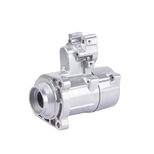
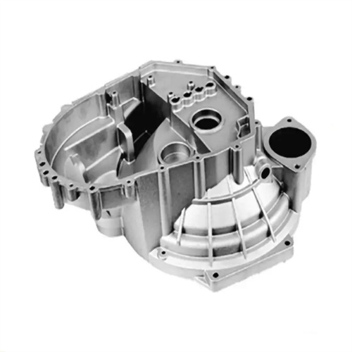
Die casting mold push tube design
The design of the push tube of the die-casting mold is a key step in ensuring the smooth demolding of special structural die-casting parts such as tubular and cylindrical parts. Its design quality is directly related to the molding accuracy of the die-casting parts and the service life of the mold. The design of the push tube must first clarify its basic functional positioning, that is, to evenly transmit the pushing force through the annular end face to avoid deformation or surface damage of the die-casting parts during the demolding process. In the initial stage of design, it is necessary to comprehensively analyze the structural parameters of the die-casting, including the inner diameter, outer diameter, length, wall thickness, and whether it has complex features such as steps and grooves. These parameters will directly determine the external dimensions, wall thickness and structural form of the push tube. For example, for thin-walled tubular die-casting parts with a wall thickness of only 1-2mm, the wall thickness of the push tube must be controlled between 3-5mm to ensure its own rigidity while avoiding increasing the weight of the mold and the difficulty of processing due to being too thick.
The material selection and heat treatment process of the push tube are important aspects that cannot be ignored in the design. Since the push tube needs to come into contact with high-temperature molten metal (such as the die-casting temperature of aluminum alloy is about 660°C) during operation and withstand repeated pushing friction, alloy tool steels with high temperature resistance and strong wear resistance, such as Cr12MoV and H13, must be selected. Among them, Cr12MoV can reach a hardness of HRC58-62 after quenching and low-temperature tempering. It has excellent wear resistance and dimensional stability and is suitable for ordinary die-casting molds for mass production; H13 steel has higher high-temperature strength and toughness. After quenching and medium-temperature tempering, it can still maintain a high hardness at 600°C, making it suitable for high-pressure and high-temperature precision die-casting scenarios. The heat treatment of the push tube must ensure uniform overall hardness to avoid premature wear due to insufficient local hardness. At the same time, quenching deformation must be controlled to ensure subsequent processing accuracy.
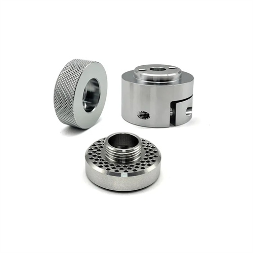
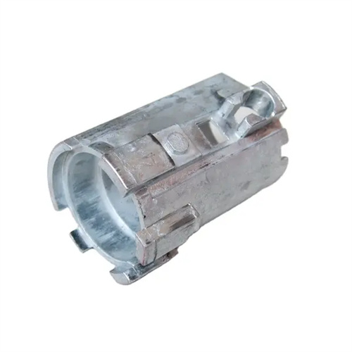
The structural design of the push tube needs to be individually optimized according to the specific shape of the die-casting. For straight-through tubular die-castings, a straight cylindrical push tube of equal diameter can be used, the inner wall of which matches the core, and the outer wall maintains a clearance fit with the mold cavity; for tubular die-castings with steps, a stepped push tube needs to be designed, and the size of each step needs to correspond to the step size of the die-casting to ensure that all parts are evenly stressed during ejection. The design of the head of the push tube is particularly critical, and usually needs to match the shape of the end face of the die-casting. If the end face of the die-casting is flat, the head of the push tube can be designed as a flat end face; if the end face of the die-casting has a boss or a pit, the head of the push tube needs to be designed with an avoidance structure to avoid damage to the die-casting during ejection. In addition, the tail of the push tube needs to be designed with a connection structure, such as steps, threads, etc., so that it can be fixedly connected to the push plate.
The fit accuracy design of the push tube and related components directly affects the working performance of the ejection mechanism. The fit between the inner wall of the push tube and the core usually adopts a clearance fit of H7/f6, and the fit clearance is generally controlled at 0.01-0.03mm. If the clearance is too small, the push tube movement will be stuck, and if it is too large, the molten metal may overflow. The fit clearance between the outer wall of the push tube and the mold cavity needs to be slightly larger than the fit clearance of the inner wall, usually 0.03-0.05mm, to avoid interference with the cavity during the movement of the push tube. The length of the push tube must be designed to ensure that the die-casting can be completely separated from the core after the ejection stroke is completed, and the tail of the push tube does not exceed the range of the ejector plate. When calculating the length of the push tube, factors such as the length of the die-casting, the ejection stroke, and the thickness of the ejector plate must be considered, and a margin of 0.5-1mm must be reserved to compensate for assembly errors and thermal expansion.
Push tube design also needs to consider mold processing technology and ease of use and maintenance. The inner and outer diameters of the push tube typically undergo grinding to ensure dimensional accuracy and surface roughness. The inner surface roughness must reach Ra0.8μm or less, and the outer surface roughness must reach Ra1.6μm or less to reduce friction. For push tubes with complex shapes, precision machining methods such as electrospark machining (EDM) or wire cutting can be used to ensure shape accuracy. During design, the push tube structure should be simplified as much as possible, avoiding overly complex internal cavities or external shapes to reduce processing difficulty and cost. Furthermore, the push tube should be removable to facilitate replacement after wear, reducing mold maintenance time and cost. The application of computer-aided design (CAD) and computer-aided manufacturing (CAM) technologies has significantly improved the design and machining accuracy of push tubes. Through 3D modeling and simulation analysis, the force state and motion trajectory of the push tube during operation can be predicted in advance, allowing for further optimization of design parameters and improving the reliability and service life of the push tube.