Design of die casting mold structural parts
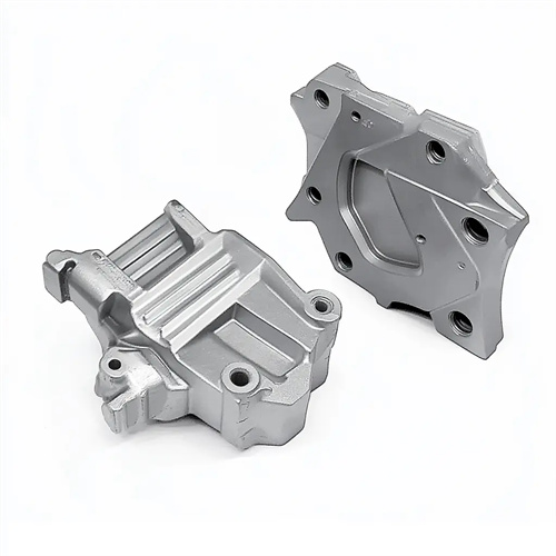
The die-casting mold structure, consisting of the fixed die plate, movable die plate, mold plate, support plate, and spacers, forms the mold’s foundational framework. Its design must ensure sufficient rigidity, strength, and precision to withstand the various forces involved in the die-casting process (such as clamping force, injection force, and impact), while also providing a stable mounting base for the molded parts and ejection mechanism. The fixed die plate connects to the die-casting machine’s fixed die plate. Its dimensions and mounting hole locations are determined by the die-casting machine model. Its thickness is typically 30-80mm, but can reach 100-150mm for larger molds. The fixed die plate is typically made of 45 steel or Q235 steel, tempered to a hardness of HB200-250 to ensure resistance to deformation under clamping forces. The mounting hole location and dimensions must be compatible with the die-casting machine. The hole diameter should be 0.5-1mm larger than the tie rod diameter, and the hole spacing tolerance should be controlled within ±0.1mm to ensure accurate mold installation. For example, the fixed die base plate used for a 1600kN die-casting machine is usually 600mm×500mm in length×width, 60mm in thickness, with a mounting hole diameter of φ50mm and a hole spacing of 400mm×300mm.
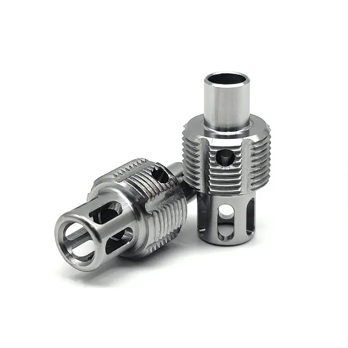
The movable die base plate is connected to the fixed plate of the die-casting movable die. In addition to meeting the same installation requirements as the fixed die base plate, it also needs to provide support for the ejection mechanism. Its thickness is usually 10-20mm larger than that of the fixed die base plate to enhance rigidity. The movable die base plate needs to have holes for the push rod and the reset rod. The position and size of the holes must correspond one-to-one with the push rod and the reset rod, and the fitting clearance must be controlled at 0.1-0.2mm to avoid movement interference. For molds with ejector cylinders, the movable die base plate also needs to be machined with a cylinder hole. The hole diameter tolerance is H7, and the fitting clearance with the ejector cylinder is 0.02-0.04mm to ensure smooth movement of the ejector cylinder. The material selection of the movable die base plate is the same as that of the fixed die base plate. For large molds subjected to large forces, steel castings (such as ZG35) can be used. They can be processed after annealing to reduce internal stress. For example, the movable die base plate of the die-casting die for large automobile chassis parts is 120mm thick and is made of ZG35 cast steel. The mounting surface is ground and the flatness error is controlled within 0.05mm/m.
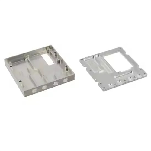
The template (including the fixed and movable templates) is a key component for mounting molded parts. Its dimensions are determined by the cavity layout and overall mold structure. Its length and width are typically 100-200mm larger than the cavity distribution area. Thickness is calculated based on cavity depth and stress conditions, generally ranging from 50-150mm. The template material must possess high strength and wear resistance. H13 steel or 4Cr5MoSiV1 steel is commonly used, achieving a hardness of HRC 30-35 after quenching and tempering. Pre-hardened steel (such as 718H) can be used for large templates to prevent post-processing deformation. The cavity mounting holes in the template must precisely align with the inserts, with a dimensional tolerance of H7, a surface roughness of Ra 0.8μm or less, and a perpendicularity error of no more than 0.01mm/100mm. Furthermore, cooling channels must be designed within the template, with a diameter of 8-16mm, a spacing of 50-100mm, and close proximity to the cavity surface (20-30mm distance) to ensure uniform cavity temperature. For example, the dynamic platen of the aluminum alloy wheel hub die-casting mold is 120mm thick and made of H13 steel. The cooling water channel is distributed in a spiral shape and is 25mm away from the cavity surface to ensure uniform cooling of all parts of the hub.
The support plate, located between the movable platen and the movable die base plate, supports the cores, withstands molding pressure, and prevents deformation. Its thickness is determined based on the core distribution and the applied forces. It is typically 40-100mm. For large molds or areas with densely distributed cores, the thickness may need to be increased to 100-150mm. The support plate is made of 45 or 50 steel, with a hardness of HB220-250 after quenching and tempering. For applications subject to higher forces, Cr12 steel can be used, with a hardness of HRC45-50 after quenching for improved wear resistance. The mating surfaces between the support plate and the movable platen must be precision-ground to a flatness tolerance of within 0.01mm/m and a contact area of at least 80% to ensure uniform force transmission. The support plate must include holes for core and push rod insertion. The holes must be positioned with the same precision as the platen, with a clearance of 0.05-0.1mm to prevent interference between the core and push rod during movement. For example, for a die-casting mold with multiple slender cores, the support plate thickness is 80mm, and the fitting clearance between the core through-hole and the core is 0.05mm to ensure that the core does not bend or deform under high pressure.
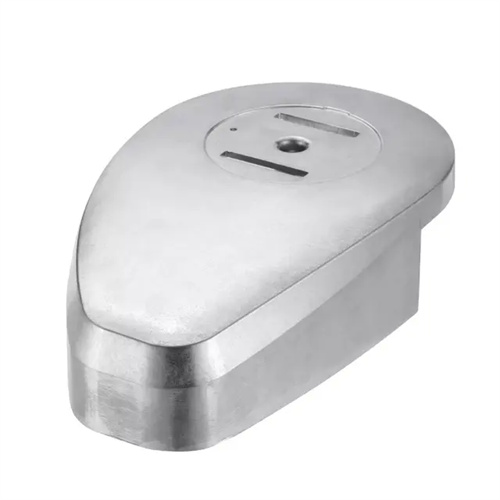
Spacers (also known as feet) support the movable mold base and adjust the mold’s closing height. Their height is determined by the ejector mechanism’s stroke, typically 50-150mm, ensuring ample clearance for the ejector plate. The spacers are the same length as the movable mold base and 50-100mm wide. Two to four spacers are typically placed symmetrically on either side of the base. The spacers are made of 45 steel, tempered to a hardness of HB220-250. They are fastened to the movable mold plate and base with bolts and positioned with locating pins to ensure consistent height. The top and bottom surfaces of the spacers must be parallel, with a parallelism error of no more than 0.01mm/100mm to prevent uneven stress on the mold plate due to height variations. For example, for a mold with an 80mm ejector stroke, the spacers should be 100mm high to ensure the ejector plate does not contact the movable mold base at maximum stroke, while also allowing a 20mm safety margin. The design of the mold structure parts needs to be considered as a whole. The force simulation of the mold body is carried out through finite element analysis software, and the thickness and layout of each part are optimized. Under the premise of ensuring strength and rigidity, the mold weight is reduced and the manufacturing cost is reduced.