Design of die-casting molded parts
The design of die-casting mold parts is a core factor in determining the quality of die-castings. It is necessary to comprehensively consider factors such as the die-casting’s geometry, dimensional accuracy, surface quality, and die-casting process characteristics to ensure that the parts can be successfully molded and meet usage requirements. Molding parts include cavities, cores, and molding inserts. The design process typically begins with a three-dimensional die-casting model analysis. Structural processability assessments determine the parting surface, gate location, and ejection method, followed by detailed structural design and parameter calculations. For example, for die-castings with side holes or undercuts, space must be reserved for the core-pulling mechanism in the molded part design, while ensuring coordination between the core-pulling and ejection actions to avoid interference.
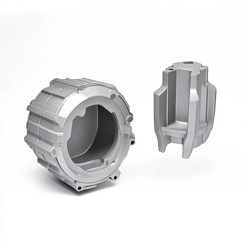
The design of the mold cavity must prioritize its structural strength and rigidity to withstand the high pressures experienced during the die-casting process (typically 40-120 MPa). Cavity wall thickness is a critical parameter. Too thin a mold will cause plastic deformation under high pressure, while too thick increases mold weight and cost, while also impacting heat dissipation. According to empirical formulas, cavity wall thickness can be calculated based on the ratio of die-casting pressure to the material’s allowable stress. For a cavity made of H13 steel, the minimum wall thickness should be no less than 15 mm at a die-casting pressure of 80 MPa. For larger cavities, the wall thickness should be increased to 20-30 mm. High surface quality is required for the inner wall of the cavity, requiring grinding and polishing to maintain a surface roughness of Ra 0.4-0.8 μm. This ensures a smooth surface finish for the die-cast part, reduces molten metal flow resistance, and facilitates demolding. Furthermore, the bottom of the cavity requires appropriate radius (typically R1-R3) to prevent stress concentration that can lead to cavity cracking.
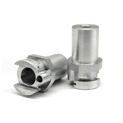
The core design must balance molding accuracy and inherent strength, especially for slender cores or those with complex shapes. Measures must be taken to prevent bending or breakage. The core’s diameter-to-length ratio is a critical design parameter. For circular cores, when the aspect ratio exceeds 10, reinforcing ribs or guide supports are required to enhance stability. For example, when forming a φ5mm deep hole in a die-cast part with a hole depth of 60mm (aspect ratio of 12), a guide sleeve is required in the middle of the core to reduce radial forces during the die-casting process. The core material selection should be determined based on the operating conditions. For standard cores, Cr12MoV steel (hardness HRC 58-62) can be used. For cores operating under high temperature and high pressure (such as when die-casting aluminum alloys), H13 steel (hardness HRC 45-50) should be used, and surface nitriding should be performed to improve wear resistance and thermal fatigue resistance. The clearance between the core and the cavity must be strictly controlled, generally 0.05-0.1mm, to ensure that the molten metal does not produce flash and to facilitate exhaust and demolding.
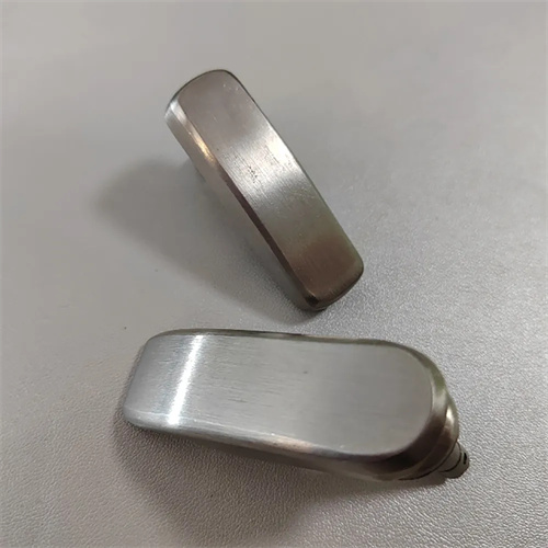
The draft angle design of molded parts is a crucial parameter for ensuring smooth demolding of die-cast parts. It must be determined based on the die-casting material, surface roughness, and height. For aluminum alloy die-castings, the draft angle for the cavity is typically 1°-3°, and for the core, 0.5°-2°. The lower the surface roughness, the smaller the required draft angle. For taller die-castings, a gradual draft angle can be used, with a smaller slope at the bottom (0.5°) and a larger slope at the top (3°). This ensures smooth demolding and reduces dimensional errors in the die-casting. Furthermore, any raised or recessed structures on the molded part require sufficient draft angle. For ribs deeper than 10mm, the draft angle should be no less than 2° to avoid damage to the die-casting surface during demolding.
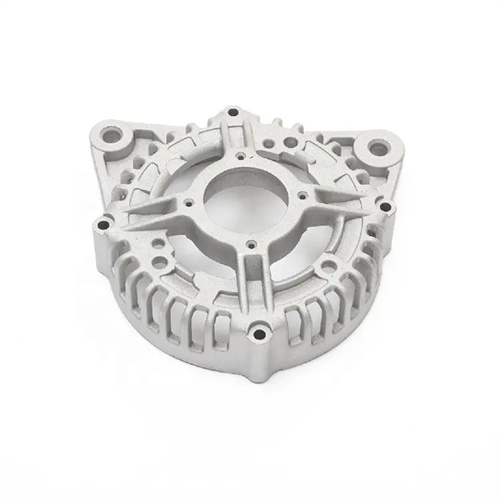
The design of the cooling system for molded parts directly impacts die-casting production efficiency and part quality, and must be developed in parallel with the structural design of the molded parts. Cooling channels should be located close to the mold cavity surface (typically 15-25 mm) and evenly distributed to ensure uniform temperature distribution across the cavity (temperature differences should not exceed ±5°C). For complex cavities, custom-shaped channels or 3D-printed conformal channels can be used, closely following the cavity contours to improve cooling efficiency. For example, in an automotive wheel die-casting mold, annular channels are used in the spoke cavity and spiral channels in the rim to ensure uniform cooling across the cavity. The diameter of the cooling channels is determined by the cavity dimensions, typically 8-16 mm, and the water flow rate is controlled between 1.5 and 3 m/s to ensure effective heat exchange. Furthermore, the cooling system should be equipped with an inlet, outlet, and exhaust valve to facilitate exhaust and adjust the water flow rate to ensure stable operation of the cooling system.