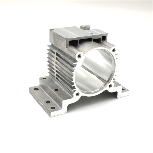
The die-casting mold platen is the fundamental load-bearing component of the mold, fulfilling crucial functions such as securing the molded part, transmitting clamping force, and guiding the mold opening and closing. Its design quality directly impacts the mold’s overall rigidity, service life, and die-casting precision. The platen’s dimensions are determined based on the cavity layout, die-casting machine specifications, and the distribution of clamping force. Its length and width must typically accommodate all cavities and auxiliary components (such as guide pins and sprue bushings) while also matching the tie-bar spacing of the die-casting machine. For example, for a mold used in a 2500kN die-casting machine, the platen’s length and width must be within 800mm x 600mm to accommodate the tie-bar spacing requirements of the die-casting machine. Platen thickness is a critical parameter, calculated based on the clamping force and cavity depth. Typically, platen thicknesses range from 50-100mm for small and medium-sized molds and from 150-250mm for large molds to ensure no plastic deformation under the clamping force (typically 40-120MPa).
The material selection for the mold plate must balance strength, wear resistance, and processability. Commonly used materials include 45 steel, H13 steel, and 718H pre-hardened steel. After quenching and tempering, 45 steel can reach a hardness of HB220-250. It is relatively low-cost and suitable for small molds subjected to low forces. H13 steel offers excellent thermal strength and wear resistance, achieving a hardness of HRC30-35 after quenching and tempering, making it suitable for medium-sized or larger or high-temperature die-casting molds (such as aluminum and magnesium alloy die-casting). 718H pre-hardened steel has a factory hardness of HRC32-36, requiring no subsequent heat treatment, reducing processing distortion, and is suitable for precision molds. For example, the movable mold plate for a large automobile engine block die-casting mold is made of H13 steel, 200mm thick, quenched and tempered, and precision machined to ensure dimensional stability. The processing accuracy of the template is required to be high. The parallelism error of the upper and lower planes is no more than 0.01mm/100mm, the flatness error is controlled within 0.02mm/m, and the surface roughness Ra is below 1.6μm to ensure good fit with adjacent components.
The cavity mounting holes on the template are key structures for securing inserts or the overall cavity. Their size and positional accuracy directly impact the dimensional accuracy of the die-cast part. The shape of the mounting hole must match the insert’s profile. Common shapes include circular, rectangular, and irregular shapes. The dimensional tolerance of the hole is typically H7, and the clearance with the insert is controlled within 0.01-0.03mm (for an interference fit, this is controlled within -0.02-0mm). The verticality error of the mounting hole should not exceed 0.01mm/100mm to ensure that the insert is perpendicular to the template plane after installation and to avoid uneven wall thickness in the die-cast part. For example, the hole for mounting a circular insert has a diameter of φ100H7 (+0.035/0), and the insert diameter is φ100m6 (+0.025/+0.012). The interference fit is 0.012-0.023mm to ensure the insert is firmly fixed. A sufficient number of screw holes and pin holes must be set around the mounting holes. The screw hole diameter is determined according to the thickness of the template (usually M8-M20), with a spacing of 50-100mm. The pin hole diameter is 0.01-0.02mm larger than the positioning pin to ensure accurate positioning of the insert.
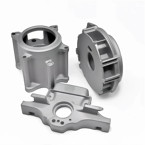
The design of the template’s guiding and positioning structure is crucial for ensuring mold opening and closing accuracy. These holes typically include guide pin holes, guide sleeve holes, and locating pin holes. The diameter tolerance of the guide pin and sleeve holes is H7, with a clearance of 0.01-0.03mm between the guide pin and sleeve. The hole positioning error should be no more than 0.01mm, ensuring precise guidance after assembly. Guide pin holes should be symmetrically distributed and generally located at the four corners of the template. Larger templates can include additional intermediate guide pin holes for enhanced guiding stability. For example, a 600mm×500mm template would have a φ35H7 guide pin hole at each corner, with a spacing of 500mm×400mm. This ensures uniform force distribution during mold opening and closing. Locating pin holes, typically located asymmetrically in the template, are used for rough positioning during mold installation. They typically have a diameter of φ10-φ20mm, an H7 tolerance, and a clearance of 0.005-0.015mm between the locating pins.
The design of the mold plate’s cooling and exhaust system must be coordinated with the mold cavity layout. Cooling channels should be located close to the cavity surface (at a distance of 20-30 mm) and evenly distributed within the mold plate. They should be connected in series or parallel to ensure uniform cavity temperature (temperature differences should not exceed ±5°C). Standard fittings (such as G1/4 and G3/8) should be provided at the inlet and outlet of the channels to facilitate connection to the cooling lines. For example, the movable platen of an aluminum alloy wheel die-casting mold features an internal spiral water channel with a diameter of φ12 mm, located 25 mm from the cavity surface. Water dividers provide independent temperature control for each zone. Venting slots in the mold plate are typically located at the parting surface or at the mating surface between the insert and the mold plate. They are 5-10 mm wide and 0.05-0.1 mm deep, connecting to the cavity and ensuring smooth exhaust during die-casting. Furthermore, lifting eyelets should be symmetrically distributed along the edges of the mold platen, with a diameter determined based on the mold weight (typically φ20-φ50 mm) to ensure safe lifting. Through 3D modeling and finite element analysis, the structural design of the template can be optimized to reduce weight and lower manufacturing costs while ensuring strength and rigidity.