Aluminum Die Casting: Mold Material Selection for Durability and Performance
Choosing the right mold material is foundational to designing effective aluminum die casting molds, as it directly impacts durability, heat resistance, and part quality. We prioritize high-grade tool steels like H13 and P20, which offer exceptional resistance to the thermal cycling and pressure inherent in die casting. H13 steel, in particular, withstands repeated exposure to molten aluminum (temperatures around 660°C) and maintains hardness after heat treatment, ensuring long mold life—often exceeding 100,000 cycles for high-volume production. For complex molds with intricate details, we sometimes use pre-hardened steels to minimize distortion during machining. Surface treatments like nitriding or chrome plating further enhance wear resistance and reduce sticking, preventing aluminum from adhering to mold surfaces. Material selection also considers cost versus performance: while premium steels have higher upfront costs, they reduce maintenance requirements and downtime, making them more economical for large production runs. By matching mold material properties to the specific alloy and production volume, we ensure consistent part quality and maximize mold longevity.
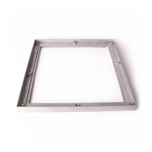
Aluminum Die Casting: Cavity and Core Design for Part Accuracy
The design of cavities and cores in aluminum die casting molds directly influences part dimensional accuracy and surface finish. We focus on creating precise cavity geometries that replicate the final part dimensions while accounting for aluminum’s shrinkage rate (typically 1-2% depending on the alloy). This requires careful calculation of shrinkage allowances during mold design to ensure cast parts meet specifications after cooling. Core design is equally critical, especially for parts with internal features like holes or threads, where cores must be precisely positioned to maintain wall thickness uniformity. We use 3D modeling to simulate how molten aluminum flows around cores, identifying potential issues like uneven filling or air entrapment. For complex parts, we may incorporate collapsible or sliding cores to produce undercuts or complex internal geometries without damaging the part during ejection. Proper cavity and core alignment is maintained through guide pins and bushings, preventing misalignment that could cause flash or dimensional errors. By optimizing cavity and core design, we ensure consistent part quality across thousands of production cycles.
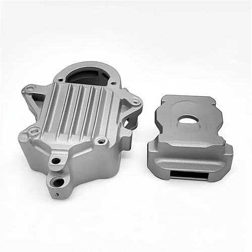
Aluminum Die Casting: Cooling System Layout for Uniform Solidification
Effective cooling system design is essential in aluminum die casting molds to ensure uniform solidification, reduce cycle times, and prevent defects like warping or porosity. We strategically place water-cooled channels throughout the mold, positioning them 10-15mm from cavity surfaces to maximize heat transfer without compromising structural integrity. For parts with varying wall thicknesses, we design non-uniform cooling circuits—closer channels near thick sections accelerate cooling, while spaced channels in thin areas prevent premature solidification. We use computational fluid dynamics (CFD) simulations to analyze heat distribution, ensuring no “hot spots” remain that could cause uneven shrinkage. Cooling channel diameter and flow rate are calibrated to achieve optimal heat removal; typically, 8-12mm diameter channels with turbulent flow (Reynolds number >2000) provide the best performance. For intricate mold sections, we implement conformal cooling using 3D-printed inserts with curved channels that follow the cavity contours. Proper cooling reduces cycle times by 20-30% and ensures dimensional stability, making it a critical consideration for high-volume aluminum die casting production.
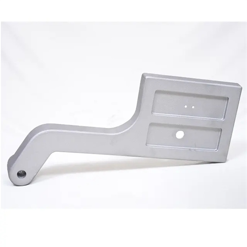
Aluminum Die Casting: Gating and Runner System Optimization for Flow Control
Gating and runner systems in aluminum die casting molds dictate how molten aluminum fills the cavity, directly affecting part quality and defect formation. We design runner systems to deliver molten aluminum evenly to the cavity while minimizing pressure loss and turbulence. Fan gates are often used for large, flat parts to ensure uniform filling, while edge gates work well for smaller components with specific flow requirements. Runner cross-sections are typically designed with a trapezoidal or circular shape to maintain laminar flow, reducing oxide formation that can cause inclusions in the cast part. Gate size is carefully calculated based on part volume and thickness—too small a gate causes excessive velocity and turbulence, while too large a gate increases cycle time and material waste. We position gates to avoid impinging on cavity walls, which can create air pockets or surface defects. Using mold flow simulation, we optimize gate location and runner geometry to ensure complete cavity filling without overflows, balancing filling time with solidification rates for consistent part quality.
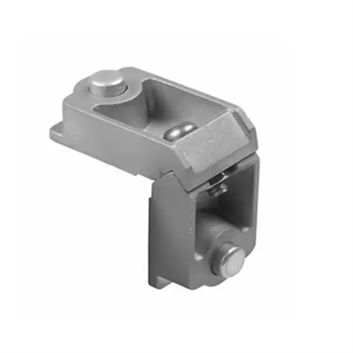
Aluminum Die Casting: Draft Angles and Fillets for Ejection and Part Integrity
Incorporating proper draft angles and fillets is crucial in aluminum die casting mold design to facilitate easy ejection and prevent part damage. Draft angles—tapered surfaces on vertical mold walls—reduce friction between the part and mold during ejection, preventing sticking and surface scuffing. We specify minimum draft angles of 0.5° per side for simple surfaces, increasing to 1-2° for deep cavities or textured surfaces where adhesion is more likely. Fillets (rounded edges) at part corners reduce stress concentrations in both the mold and the cast part, preventing crack formation during cooling and ejection. Internal corners typically require larger fillets (1-3mm radius) than external corners to accommodate proper metal flow and avoid sharp edges that can cause mold wear. These design features also improve molten aluminum flow, ensuring complete cavity filling in intricate areas. By integrating adequate draft angles and fillets, we reduce ejection force requirements, extend mold life, and produce parts with smoother surfaces and better structural integrity.
Aluminum Die Casting: Venting System Design for Air and Gas Release
Effective venting systems are vital in aluminum die casting molds to prevent air and gas entrapment, which can cause porosity, incomplete filling, or surface defects. We design vents as narrow channels (0.02-0.05mm thick) along cavity edges, parting lines, and deep recesses where air is most likely to become trapped. Vents connect to overflow wells that collect excess molten aluminum and trapped gases, preventing them from re-entering the cavity. For complex geometries, we incorporate venting into sliding cores and lifters to release gas from internal features. The total vent area is carefully calculated based on part volume and filling time, ensuring sufficient gas escape without allowing excessive flash formation. We also use porous metal vents in critical areas for high-volume production, as they provide consistent venting over extended cycles. Proper vent maintenance is factored into mold design, with accessible vent locations that allow easy cleaning to prevent clogging from oxide buildup. By prioritizing venting system design, we ensure complete cavity filling and produce aluminum die cast parts with minimal internal defects.